Archived Projects
Summary
2017-19 | ArdSimX Interface
2015-17 | ArdSim Library
2014-15 | ARDref Interface
2013-14 | XPData library
2012-13 | Baron 58 program
2011-12 | First Tests with UDP
The XPlaneData a Library (later XPData) project was started (in 2014) to unificate of all our previous X-plane interface code samples.
The XPlaneData library provides network interaction between Arduino and X-Plane and includes functions for easy assignment different types of input, including common buttons, switches, encoders to each Arduino pins and functions for transmission of control data to X-Plane.
You can use library functions to assign specific commands or datarefs for chosen pins as arguments of the control functions in your Arduino code. This makes the Arduino programming for users quite simple - you need to write down specific function (button, switch, encoder, axes, LED output, etc.) and add pin number and dataref/command as arguments.No other software and plugin is needed! All data is transmitted directly to X-Plane using its built-in UDP protocol.
You can use as many Arduino boards with XPData input library as you need to. All boards should have an Ethernet shield (or module) connected to your LAN.
| Header | Index | 32 bytes of Data - 8 sim parameters in the format of 4-byte floating point numbers | Index | Next data | |||||||
| 68-65-84-65-60 | 67-0-0-0 | 252-163-78-63 | 154-242-71-63 | 167-252-81-63 | 0-0-128-63 | 0-0-128-63 | 0-0-128-63 | 0-0-128-63 | 0-0-128-63 | 68-0-0-0 | 245-230-128-63 |
Flaps = ReadData ( 13, 5 );
Some functions can use data to directly send values on the output devices :
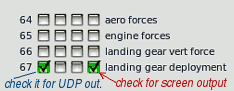
LEDout (13, 127, 6); // Control the LED on the pin #13 by data from group #127/6 ("Gear Warning")
Button ( Pin, Cmd ) ; | Button function (for commands). It activates one command when pressed. Use for toggle buttons to change the parameter's state or for one-command button to set parameter once pressed (or one position for the multi-position switch is chosen). |
| Arguments used: 1) the pin number for the button, 2) Command string (or defined name (#define operatior) of the command) | |
| Button ( 2, "radios/com1_standy_flip" ); Button ( 25, "flight_controls/landing_gear_up" ); Button ( 5, "v" ); | example 1 - toggle button connected to Pin# 2, Com1 frequency flip example 2 - "Set" button for Gear lever (pin #25) example 4 - Emulates the "v" char of the keyboard (default turns parking brake on/off) |
| The "Button()" function can be used as "Continuous command button" or "Click and hold to repeat" button together with the Repeat() function | |
Button ( Pin, Dref, Val ) | Button function for datarefs. The same function, but used with datarefs (set dataref value when clicked) |
| Arguments used: 1)- the pin number for this button, 2)- Dataref string (or defined name for this dataref), 3)- Value dataref is taken when button is clicked | |
| Button_D ( 7, "cockpit2/controls/flap_ratio", "0", 0,5 ); | example - "Set" button for multi-position flaps lever, (position on the Pin# 7) |
Repeat ( Pin, Mode ) | Repeat function for the button. Placed directly after the "Button()" function with the same pin#. Has two mode - "Continuous command button" and "Click and repeat after hold delay" |
| Button ( 8, "annunciator/test_all_annunciators"); Repeat ( 8, 2 ); | Mode 2 - "Continuous command button". It continuously activates the command while pressed. Use for the command to be sent continuously to work, such as "Test annunciators" |
| Button ( 12, "radios/obs_HSI_up"); Repeat ( 12, 1 ); | Mode 1 - Work as simple button when clicked once and start repeating after 0.8 sec when hold. Use it for increment value button (can be used instead of encoder): |
MPrepeat ( Pin, Mode ) | The same as above Repeat function, but for the Multi-position analog input! Argument "Pin" - is the position number, not the pin #. |
Toggle ( Pin, Cmd1, Cmd2 ) | Toggle switch (for commands). With this function you can assign the switch as input actuator for the chosen pin. For the switch shoud be used a couple of commands. |
| Toggle ( 9, "systems/avionics_on","systems/avionics_off" ); Toggle ( 11, "lights/nav_lights_on", "lights/nav_lights_off" ); |
Toggle (on/off) Switch - activates one command when it is in one position and sends the other command when toggled into the second position. |
Toggle ( Pin, Dref, N, Val1, Val2 ) | Toggle switch (for Datarefs). With this function you can assign the switch as input actuator for the chosen pin. For the switch shoud be used one dataref with two values |
| Toggle (42, "cockpit2/Togglees/landing_lights_Toggle", 2, 1,0 ); Toggle (7, "cockpit2/radios/actuators/RMI_left_use_adf_pilot", 0, 1,0 ); |
Toggle (on/off) Switch when DataRefs used - toggles between two values for one dataref. For simple toggle use 1 and 0 value, but you can assign any other needed values (such as 0.5 / 1, etc.)) |
Encoder ( Pin, Cmd1, Cmd2, Type ) | Encoder (for commands). Assign encoder for two commands. As arguments, define first Pin number, two commands and encoder type (0,1,2). . |
| Encoder (42, "radios/obs_HSI_down", "radios/obs_HSI_up", 0 ); Encoder (30, "radios/stby_com1_fine_up", "radios/stby_com1_fine_down", 2 ); |
- Encoder Type 0 connecte to the pins 42-43 - HSI Heading knob - Encoder Type 2 on the bus pins #30-31 - Radio Com1 frequency |
Encoder_D ( Pin, Dref, Val, Inc, Type ) | Encoder (for datarefs). Assign encoder for one dataref. As arguments, define 1) first Pin number, 2) Dataref, 3) Current value of dataref, 4) Increment/Decrement value for one step 5) Encoder type (0,1,2). . |
| First, you should assign the variable for the parameter to be controlled when used dataref for encoder: float HSI; | |
| HSI = Encoder_D (42, "cockpit2/radios/actuators/hsi_obs_deg_mag_pilot[0]", HSI, 1, 0 ); | |
Mode ( Pin ) | Mode for input pins. Simple function to read current state of any inputs (pin #0-49 or pins #100-227 for Bus extension). Returns "0" or "1". Can be used for built-in encoder button, for creating your custom code behaviour. |
| enc = Mode ( 5 ); | - Check the pin #5 state. Variable "enc" set to 0 or 1 |
| btn = Mode(148); if (btn) adf++; if (adf == 3) adf = 0; | - When button on the pin #148 is clicked, the "btn" will change its value from 0, 1, 2, 0... in cycle (for ADF frequency input encoder mode ) |
if (enc==1) Encoder ( 38, "radios/stby_com1_fine_up","radios/stby_com1_fine_down", 0 ); // Com1 frequency fine if button "enc" is pressed else Encoder ( 38, "radios/stby_com1_coarse_up", "radios/stby_com1_coarse_down", 0 ); // Com1 frequency coarse if button "enc" is released |
|
MultiPosition ( APin, Pos ) | Function for creating multi-position Rotary Switch or Button Array connected to one analog pin. Define: 1) pin number, 2) Number of positions for rotary switch or number of buttons for button array. |
| When command are needed for contol, use the associated function "MPcom()" for each position: | |
| MultiPosition(1, 5); MPcom (1, "magnetos/magnetos_off_1"); MPcom (2, "magnetos/magnetos_right_1"); MPcom (3, "magnetos/magnetos_left_1"); MPcom (4, "magnetos/magnetos_both_1"); MPcom (5, "starters/engage_starter_1"); MPrepeat(5,1); |
- Define the 5-position Rotatry Switch on the analog input #1 and check its state - position #1 - Magneto off - position #2 - Magneto right - position #3 - Magneto left - position #4 - Magneto both - position #5 - Starter On and repeat when hold position |
| When dataref are needed for contol, use the associated function "MPdref()" for each position: | |
| MultiPosition(1, 3); MPdref (1, "cockpit2/radios/actuators/HSI_source_select_pilot[0]", 0); MPdref (2, "cockpit2/radios/actuators/HSI_source_select_pilot[0]", 1); MPdref (3, "cockpit2/radios/actuators/HSI_source_select_pilot[0]", 2); |
- Define the 3-position Rotatry Switch on the analog input #1 and check its state - position #1 - HSI source NAV1 - position #2 - HSI source NAV2 - position #3 - HSI source GPS |
AnalogIn ( Pin, Dref, min, max, Prec ) | Used for reading the changing values of potentiometer or some other analog device, connected to analog pin. Define: 1) pin number, 2) Dataref string, 3) The minimum and 4) maximum values for chosen dataref, 5) - precision. |
| The last number (Prec) is the number of steps or positions for desired precision , from 2 to 1000 (when using 2 - it can be the simple toggle switch) | |
| AnalogIn ( 0, "cockpit2/controls/yoke_pitch_ratio[0]", -1, 1, 500 ); AnalogIn ( 1, "cockpit2/controls/flap_ratio[0]", 0, 1, 5); | // Yoke Pitch axis, precision 500 steps // Flaps, 5 positions precision |
LEDout ( NAME )LEDout ( P, D, V, M, I ) |
Control the LED output with specific dataref. You can use this function with one argument that is previously defined constant "NAME" ( it is preferable), or use all 2-5 arguments directly without defining the named constant | LEDout ( Pitot ); LEDout ( Flaps) LEDout (8, 5, 0.5) LEDout (10, 6, 0.4, 0,8, 1) |
When defining the constant "NAME" in the beginning of the code you should assign at least two elements - the pin number for this LED output (P) and the dataref number (D). Next optional elements is the value of dataref on wich the LED should light up (V), another value of dataref for the value range (M). Last optional element "I" used to set inversion. Default V = 1, it means the LED is on when value =1. #define NAME P, D, V, M, I | ||
|
#define Pitot 10, 5 #define PitotHeat 10, 5, 0 #define Flaps1 11, 6, 0.5 #define Flaps2 12, 6, 0.4, 0.7 #define Flaps3 13, 6, 0.4, 0.7, 1 |
- Define Pitot LED connected to pin #10 and controlled by dataref #5 - The same as above but inverted output - the LED is on when value of dataref is 0 - Flaps LED on the pin #11, dataref #6, controlling dataref value = 0.5 - Flaps LED on the pin #12, dataref #6, controlling dataref range is 0.4-0.7 - Flaps LED on the pin #13, dataref #6, controlling dataref range is 0.4-0.7, inverted | |
|
LEDout ( Pitot )
LEDout ( Flaps1 ) LEDout ( Flaps2 ) LEDout ( Flaps3 ) |
// - Pitot LED on the pin #10, dataref #5. LED is on when value of dataref is 1
// - LED is ON only when flaps position = 0.5 ( useful for mutiple LEDs for one data range ) // - LED is ON when dataref value is in 0.4-0,7 range // - LED is ON when dataref value is outside of 0.4-0,7 range | |
LEDout ( Pin, State ) | Direct control of the LED. You can use this function if you need control the LED from your code | LEDout ( 13, ON ); LEDout ( 12, OFF) |
|
if (your_condition==1) LEDout (13, ON); if (your_condition==0) LEDout (13, OFF); |
// -- Turn the LED on the pin #13 ON if your condition is 1 // -- Turn the LED on the pin #13 OFF if your condition is 0 |
|
servoGauge ( Dref, ServoName ) | Assign which dataref (number "Dref") will be "linked" with a specific predefined servo ("ServoName"). | servoGauge ( 6, Flaps ); |
|
The first argument (Dref) is the dataref number which is assigned for this dataref in the "out_1.cfg" file: The second argument in this function ("ServoName") is the name of the preliminary defined construction in the beginning of your Arduino code. For example define the "Flaps" servo with control pulse range of 600-2200 mcsec connected to the pin #40, and dataref value range to control this servo 0.00 to 1.00 : #define Flaps 40, 0, 1, 600, 2200 .. where after the defined name ( Flaps ) you have to write five numbers: 1) Number of the Arduino Pin to which this servo is connected (pin #40 here) 2) Minimum value for the given dataref (0.00) 3) Maximum value for the given dataref (1.00) 4) The microseconds number which corresponds to the minimum value of dataref (560 here) 4) The microseconds number which corresponds to the maximum value of dataref (2100 here) How to define the range of your particular servo: Servo control | ||
|
Then place the servoGauge function for this example in the main code loop: servoGauge ( 6, Flaps ) | ||
Gauge ( Dref, GaugeName ) | Assign which dataref (number "Dref") will be "linked" with a specific predefined servo ("GaugeName"). | Gauge ( 6, Flaps ); |
|
The first argument (Dref) is the dataref number which is assigned for this dataref in the "out_1.cfg" file: The second argument in this function ("ServoName") is the name of the preliminary defined construction in the beginning of your Arduino code. For example define the "Flaps" servo with dataref value range to control this servo 0.00 to 1.00 : #define Flaps 5, 0, 1 .. where after the defined name ( Flaps ) you have to write 3 numbers: 1) Number of the Arduino Pin to which this servo is connected (pin #5 here) 2) Minimum value for the given dataref (0.00) 3) Maximum value for the given dataref (1.00) | ||
|
Then place the Gauge function for this example in the main code loop: Gauge ( 6, Flaps ) | ||
/*
base code template for one-engine piston airplane.
(as Cessna-172, Cessna-182. etc) using XPData library
for X-Plane Simulator.
Inputs only
XPlaneData Library
by Vlad Sychev 2014-15
http://simvim.com
*/
//---------------------------
#include <SPI.h>
#include <Ethernet.h>
#include <XPData.h> // -- include XPlaneData library
//-----------------------------
byte MAC[] = {0xDE, 0xAD, 0xBE, 0xEF, 0xFE, 0xED}; // MAC-Address of Arduino Ethernet shield
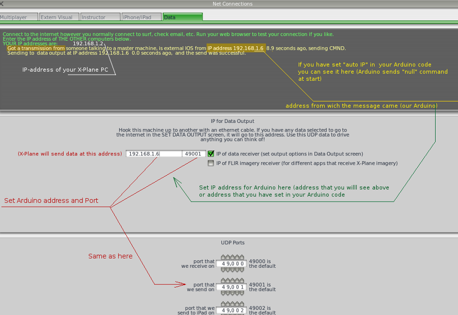
unsigned int XPR = 49001; // or 5080, if plugin // port to to receive data from X-Plane
unsigned int XPW = 49000; // port to send data to X-Plane
byte IP[] = {192, 168, 1, 10}; // This Arduino IP address (0,0,0,0 - for auto)
//------------------------------------
int enc; // Encoders built-in button
int adf; // ADF encoder built-in button status (cyclic 3-digits positions )
void setup()
{
XPDStart (XPR, XPW, MAC, IP); //==! init XPlaneData
}
//---------------------------------------------------
void loop()
{
XPDScan();
// ------ 3-Axis -------------
AnalogIn (0, "cockpit2/controls/yoke_pitch_ratio[0]", -1, 1, 500); // Pitch yoke, precision 500
AnalogIn (1, "cockpit2/controls/yoke_roll_ratio[0]", -1, 1, 500); // Roll yoke, precision 500
AnalogIn (2, "cockpit2/controls/yoke_heading_ratio[0]", -1, 1, 500); // Rudder, precision 1000
//=== Throttle ---------
AnalogIn (3, "cockpit2/engine/actuators/throttle_ratio[0]", 0, 1, 300); // Throttle, precision 300
//========================= Prop Pitch Angle for Cessna 182 etc. (2 variants) ---------
AnalogIn(4, "cockpit2/engine/actuators/prop_pitch_deg[0]", 0, 60, 300); //
//AnalogIn(4, "cockpit2/engine/actuators/prop_rotation_speed_rad_sec[0]", 0, 300, 300); //
//=======================================- Mixture ---------
AnalogIn(5, "cockpit2/engine/actuators/mixture_ratio[0]", 0, 1, 300); //
//================================== Flaps ( DREF packet ) ================================
//-------Connect to analog input potentiometer 10 kOm - and make lever with several fixed positions (if needed)
//-------( must be the full stroke of potentiometer, use the gears )
AnalogIn(6, "cockpit2/controls/flap_ratio[0]", 0, 1, 4); // Flaps, 5 positions precision
//=======================================- Starter/Magnetos =======================================
MultiPosition(7, 5);
MPcom(1, "magnetos/magnetos_off_1");
MPcom(2, "magnetos/magnetos_right_1");
MPcom(3, "magnetos/magnetos_left_1");
MPcom(4, "magnetos/magnetos_both_1");
MPcom(5, "starters/engage_starter_1"); MPrepeat(5,1);
//=======================================- Transponder Mode Switch ===================================
//------------------------ 6 positions Transponder Mode ------------------------------
MultiPosition(8, 5);
MPcom(1, "transponder/transponder_off"); // - OFF
MPcom(2, "transponder/transponder_standby"); // - STBY
MPcom(3, "transponder/transponder_alt"); // - ALT mode
MPcom(4, "transponder/transponder_test"); // - TEST mode
MPcom(5, "transponder/transponder_on"); // - ON mode
MPcom(6, "transponder/transponder_ground"); // - GND mode
//======================= Panel/Radio Lighting Brightness ( DREF packet ) =============================
AnalogIn(9, "cockpit2/switches/instrument_brightness_ratio[0]", 0, 1, 100);
AnalogIn(10, "cockpit2/switches/instrument_brightness_ratio[1]", 0, 1, 100);
//============================ Digital inputs section ===================================================
// ---- Toogles and Buttons
Toggle (13, "systems/avionics_on", "systems/avionics_off"); /* Master Avionics switch (active "1") Pin#13 must be connected
to the GND through resistor 5-10k ("pulldown" resistor)
active toggle must connect Pin #13 to the +5v
*/
// all other buttons/toggles connects pins to the GND (active state - "0"), no resistors are used:
Toggle (12, "electrical/generator_1_off", "electrical/generator_1_on"); // Alternator switch
Toggle (11, "electrical/battery_1_on", "electrical/battery_1_off"); // BATTERY switch
Toggle (9, "lights/beacon_lights_on", "lights/beacon_lights_off"); // Beacon Light switch
Toggle (8, "lights/strobe_lights_on", "lights/strobe_lights_off"); // Strobe Light switch
Toggle (7, "lights/nav_lights_on", "lights/nav_lights_off"); // NAV light switch
Toggle (6, "lights/taxi_lights_on", "lights/taxi_lights_off"); // Taxi light switch
Toggle_D (5, "cockpit2/switches/landing_lights_on[0]", 0, 1); //-- Landing Lights ---
Toggle (3, "fuel/fuel_pump_1_on", "fuel/fuel_pump_1_off"); // FUEL Pump
Toggle (2, "ice/pitot_heat0_on", "ice/pitot_heat0_off"); // Pitot Heat switch
Button (1, "flight_controls/landing_gear_up"); //---- GEAR UP
Button (0, "flight_controls/landing_gear_down"); //---- GEAR DN
//============ Audio selector Panel (7 buttons on the pins #14-20 ) - for X-Plane 10 only
Button (14, "audio_panel/monitor_audio_com1"); // A_Com1
Button (15, "audio_panel/monitor_audio_com2"); // A_Com2
Button (16, "audio_panel/monitor_audio_nav1"); // A_Nav1
Button (17, "audio_panel/monitor_audio_nav2"); // A_Nav2
Button (18, "audio_panel/monitor_audio_adf1"); // A_Adf 1
Button (19, "audio_panel/monitor_audio_dme"); // A_DME
Button (20, "audio_panel/monitor_audio_mkr"); // A_Mkr
Button (21, "transponder/transponder_ident"); //------Transponder IDENT button ----
Button(22, "radios/com1_standy_flip"); //-- Com1/Com1-stby flip
Button(23, "radios/nav1_standy_flip"); //--- NAV1/NAV1-stby flip
Button(24, "radios/com2_standy_flip"); //--- Com2/Com2-stby flip
Button(25, "radios/nav2_standy_flip"); //--- NAV2/NAV2-stby flip
Button(26, "radios/adf1_standy_flip"); //--- Change ADF stdby Freq
enc = Mode(27);
if (enc) { adf++; if (adf == 3) adf = 0; delay(15); }
//--- Encoders button PUSH/OFF
//for ADF: push one = "1"; push two = "10", push three = "100"
//=================================== Encoders Section ==================
//------! encoders use paired inputs - 28-29, 30-31, 32-33, 34-35... ... 48-49, common pin is connected to "GND"
// -----!- Encoders for Com/Nav have the built-in Push Button (If Pressed - fine up/dn) - Pin #27
if(enc) Encoder(28, "radios/stby_com1_fine_up", "radios/stby_com1_fine_down", 0); // Com1 Freq
else Encoder(28, "radios/stby_com1_coarse_up", "radios/stby_com1_coarse_down", 0);
if(enc) Encoder(30, "radios/stby_com2_fine_up", "radios/stby_com2_fine_down", 0); // Com2 Freq
else Encoder(30, "radios/stby_com2_coarse_up", "radios/stby_com2_coarse_down", 0);
if(enc) Encoder(32, "radios/stby_nav1_fine_up", "radios/stby_nav1_fine_down", 0); // Nav1 Freq
else Encoder(32, "radios/stby_nav1_coarse_up", "radios/stby_nav1_coarse_down", 0);
if(enc) Encoder(34, "radios/stby_nav2_fine_up", "radios/stby_nav2_fine_down", 0); // Nav2 Freq
else Encoder(34, "radios/stby_nav2_coarse_up", "radios/stby_nav2_coarse_down", 0);
if(adf==0) Encoder(36, "radios/stby_adf1_ones_up", "radios/stby_adf1_ones_down", 0); // ADF Freq 1
if(adf==1) Encoder(36, "radios/stby_adf1_tens_up", "radios/stby_adf1_tens_down", 0); // ADF Freq 10
if(adf==2) Encoder(36, "radios/stby_adf1_hundreds_up", "radios/stby_adf1_hundreds_down", 0); // ADF Freq 100
Encoder(38, "radios/obs2_up", "radios/obs2_down", 0); // Nav2 OBS
Encoder(40, "instruments/barometer_up", "instruments/barometer_down", 0); // Barometer, alt
//---------------- Transponder code (4 encoders on the pins #42-43, 44-45, 46-47, 48-49
Encoder(42, "transponder/transponder_ones_up", "transponder/transponder_ones_down", 0); // Transponder 1
Encoder(44, "transponder/transponder_tens_up", "transponder/transponder_tens_down", 0); // Transponder 10
Encoder(46, "transponder/transponder_hundreds_up", "transponder/transponder_hundreds_down", 0); // Transponder 100
Encoder(48, "transponder/transponder_thousands_up", "transponder/transponder_thousands_down", 0); // Transponder 1000
//---------------------------------------
} //=========--- end
/*
Don't leave in the final code any lines with Serial.print(), that you could used for testing!
That will take a lot of processing time, and lead to encoders timing inconsistency.
Comment or delete the lines with Serial.print() !
If you're not using some analog input, which has active code - connect it to GND, or "comment' this part of code!
(Or it will constantly send interference data and take time too)
by Vlad Sychev .2014-2015
*/