
An option for driving multiple LEDs in a SimVimX system is to use constant current LED driver ICs such as the DM13A and similar, which are the same latch shift registers as the 74HC595 but have 16 outputs, use a common anode connection for the LEDs, and do not require resistors for each LED.
You need to connect common GND, 3 signal lines - two common "D/L" lines and one control signal "PIN" connected to the assigned pin or multiplexer output. The driver chip itself can be powered using +5V output pin located on the master board or the same dedicated power source (+Vled +5V) used for all LEDs (in this case don't connect VDD to the +5v pin on your Arduino!):
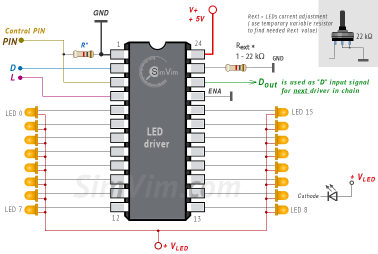
The LED operating current is set with one reference resistor connected to the Rext input (terminal #23), that can have resistance between 1 ... 22 kΩ and defines the current (and brightness) for all LEDs. You can connect a variable resistor to adjust the current as needed and then replace it by a constant resistor.
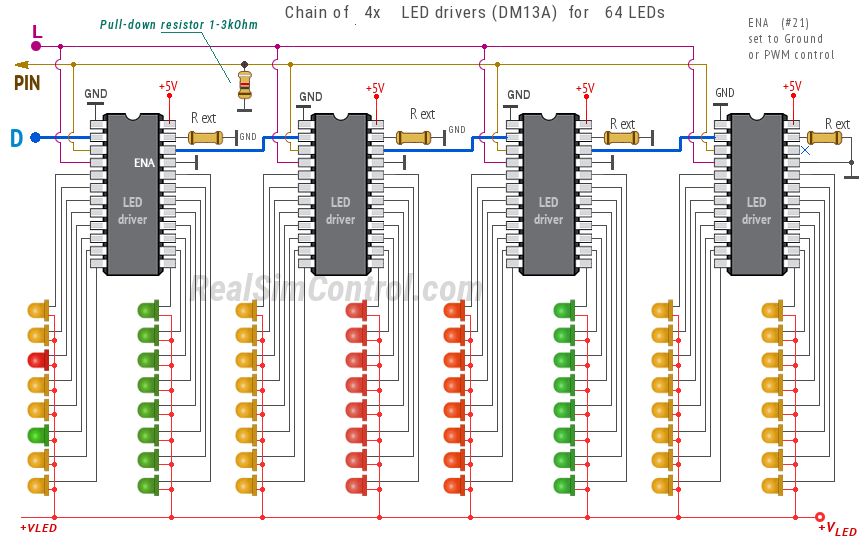
The maximum number of LEDs with serial shift control on one output is 64, for that you can use 4 daisy-chain connected DM13A drivers. For this you need to use the driver's Dout terminal #22 as "D" input signal for next driver in chain.
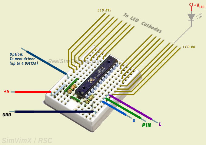
I didn't find any ready-made expansion boards with such LED drivers but you don't necessarily need them. You can use a bare DM13A chip inserted into the small "breadboard" that can be taped to any part of your cockpit, or simply glued near to the group of LEDs ( see an example).
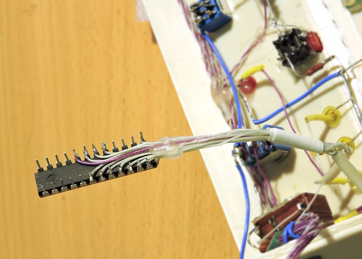
Also, using DM13A drivers in DIP casing, you can solder thin wires directly to the driver pins. Then this driver can be attached to the surface near the LED group using thermo-glue or 2-side duct tape.
See more tips about wiring your cockpit on the "Wiring" page.
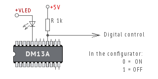
Same as for direct outputs, you can use a serial output as "On/Off" control signal for other circuits, relays, MOSFETs, etc.
For this, instead of LED, use a pull-up resistor 1k connected to +5v bus and use this terminal as output pin for digital control. In the picture you can see that output terminal #16 is used as digital output (all others can be used either for LEDs or digital outputs as well).
LED CONTROL OPTIONS
74HC595 Shift Registers DM13A LED Drivers MAX7219 LED Matrix MUX for LED Drivers LED Bar Graph Indicator Direct Connection LED Configuration