Archived Projects
Summary
2017-19 | ArdSimX Interface
2015-17 | ArdSim Library
2014-15 | ARDref Interface
2013-14 | XPData library
2012-13 | Baron 58 program
2011-12 | First Tests with UDP
NOTE: The information below is related to the ArdSimX interface only!
Use our latest SimVimX System to control more LEDs, 7-segmet and LCD displays.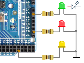
1. To control a low-power LED with Arduino simply connect it to output pins (anode) and to the ground (cathode) with serial resistor. This resistor can be varied from 50 to 1000 ohm for common LEDs with 10-30 mA current (maximum current for Arduino I/O pin starts with 40 mA).
You can select a suitable resistor by trying and checking the brightness you need. You can use about 20-30 LEDs (20mA each) if they could be turned ON all at once ( or more if there will be no one moment of such simultaneous powering ).
If you need to control a high-power LED (more than 40mA) or several parallel LEDs with Arduino (or filament lamp), use any suitable n-p-n transistor (or MOSFET) as power switch and additional power source.
Serial digital output uses several shift registers (74HC595 ICs) to extend outputs count to any number and minimize the usage of Arduino pins for output. This type of output can be used for groups of indicators (LEDs) connected to Arduino using chain of registers 74HC595. It can be used as output to control any other digital output devices (On/Off type)
This is a bit more complex then direct, but widely used method of LED output with Arduino. The data is transmitted to registers from one output pin of Arduino, 2 other pins (common "D" and "L") are used for strobe and latch data.
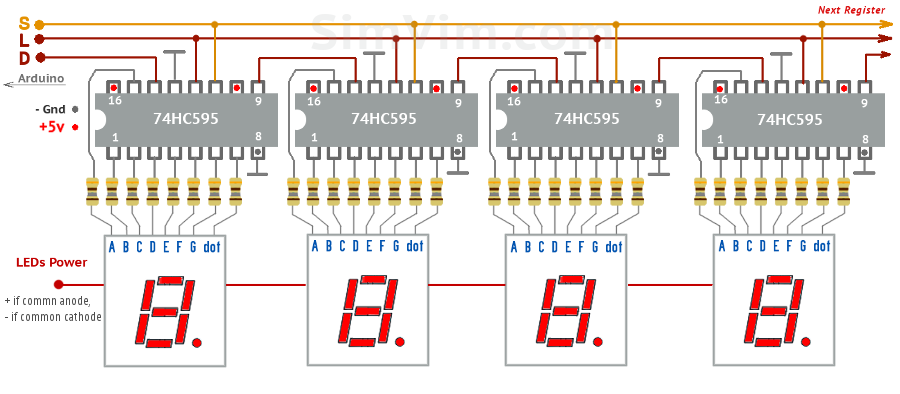
ArdSimX includes inbuilt functions to support of multiple shift-and-latch register ICs (74HC595) in chain connection that allow you to extend the number of LEDs to 8 with one register, 16 with two, 32 with 4 registers and so on..., using 3 output pins for all these LEDs (D, S , L signals in diagram below).
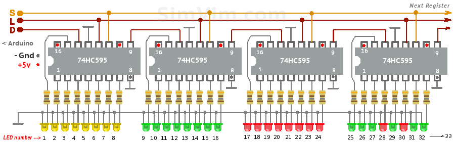
The first register is on the left side of the diagram (left-to-right numbering). In this example a total of 32 LEDs can be connected, LED #1 is on the left, LED #32 on the right.
Note: Use additional +5v power source for registers if you have more than 2-3 of them.
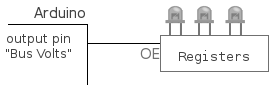
Shutting off LED groups can be done using the common OE pin of the registers.
If you don't want or can't make boards with registers yourself (or use a breadboard), you can buy some breakout boards that include 595 register with headers or contact pads, (just add a resistor for each LED).
Using the common OE pin (#13) of the registers you can shut all indicators off, not the registers controlling them, so that they still will display the same data when turned on again.
ArdSimX supports only one method of 7-segment displays - using the shift registers without multiplexing, when each 7-segment indicator is connected to its own shift register with latch (storage), and every next register is connected in a chain to the previous one. This method allows the use of single 7-segment indicators of any size and combining as many of them as needed into one display.
As default, the 74HC595 shift registers are used for displays.
NOTE: in the latest SimVimX System you can use various 7-segment displays, pre-assembled modules directly, without programming/libraries and they are all very easy to configure.
One output pin is configured as "S signal" for each particular display. Other two pins ("D" and "L" signals) are configured once and used for all registers connected to one Arduino. See the "Config Guide".
Online configurator allows you to set any suitable display mode - number of digits in display, dot type and placement, indicator type (common cathode or anode), reversed digits order (if you have modules with backward indicators wiring) etc.
Shutting off displays can be done using the common OE pin (#13) of the registers (see below on this page). The brightness can also be controlled with this pin using PWM, or by connecting the power of the 7-segment indicators through a potentiometer or a MOSFET.
Using the common OE pin (#13) of the registers you can shut 7-segment indicators off, not the registers controlling them, so that they still will display the same data when turned on again.
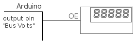
The indicators will now shut off when bus voltage failure occurs.
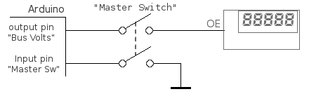

Take a double linked switch for your Master Switch. Use one pair as usual, one wire on the ground, and the other on the Arduino input pin configured for "Master Avionic" switch control in X-Plane.
The second contact pair is used to connect/disconnect the previously described bus voltage indication pin with the registers OE input (to disable the indicators).
You can power each 7-segment display using voltage (current) regulator to change the brightness of each display independently manually.
NOTE: in new SimVimX System using the PWM, Servo and Steppers is much more convenient and simple - you only need to assign parameters, connect your gauges and calibrate them directly from the SimVim plugin menu.
NOTE: The information below is related to the ArdSimX interface only!
Before doing servo configuration, you need to do some research work for your servo - test each of them to find out their minimum and maximum control pulse width in microseconds (put a sticker with these values on every servo), define rotation angle range. If needed, define interim linear segmets (up to 10) on the scale for non-linear output.
 Notes:
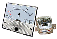
Any moving-coil milliammeter can be used as a gauge for your cockpit simulator. It's an easy and convinient way to make the instrument that have a limited needle rotation angle (moving-coil ammeters can have the scale varied from 90 to 200 degrees).
Before using your coil gauge you need to know milliammeter characteristics and calibrate it using resisors/potentiometers.
Just connect your ammeter to the PWM output through a current limiting resistor, with the other wire of the gauge connected to the ground. This resistor can be varied from 5 to 100 kohm depending of the gauge you will use:
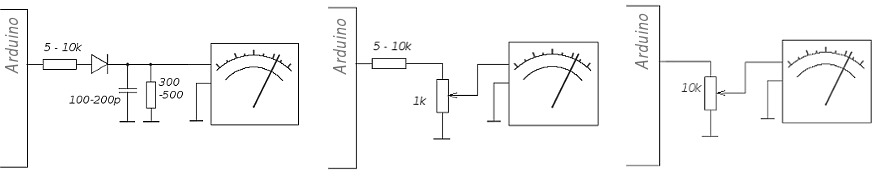
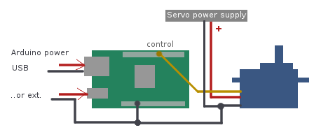
To get analog gauges working with Arduino digital outputs the Pulse Width Modulation (PWM) is used. But you can not use any Arduino pins for this - the number of-PWM controlled pins is limited. On most Arduino boards (including Uno, Nano, Mini, Leonardo), PWM output works only on pins 3, 5, 6, and 9, 10, 11. On Arduino Mega, you can use much more PWM gauges on pins #2...13 and 44...46.
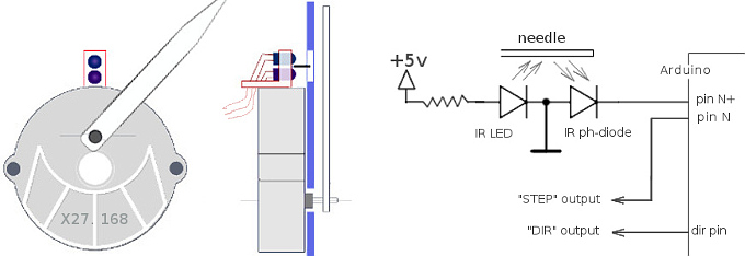
As default, ArdSimX works with a bipolar stepper motors used in car dashboard instruments (X25, X27, VID29 and similar) with external stepper motor controllers (VID6606, STI6606Z).
All details on how to control stepper motors and use stepper controllers you can read in the SimVimX System website. In ArdSimX all connections related to driver wiring are the same, besides the fact that in SimVim all steppers are connected to one multiplexer and in ArdSimX every stepper uses it's own separate Arduino pin.
These stepper controllers have two main control inputs - "DIR" and "STEP" for each one motor. All "DIR" inputs of all connected steppers are combined and use one output pin ("D") pre-assigned. Each "STEP" input is connected to one assigned in the configurator Arduino pin, plus one common "Direction" pin for all steppers.
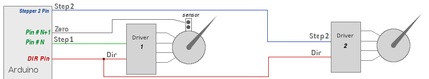
Note: in ArdSimX, for the stepper with positioning sensor one more Arduino pin is used as sensor input. This pin always follows the "step" pin assigned for this stepper (N - "step" pin number, N+1 - sensor pin number).