Archived Projects
Summary
2017-19 | ArdSimX Interface
2015-17 | ArdSim Library
2014-15 | ARDref Interface
2013-14 | XPData library
2012-13 | Baron 58 program
2011-12 | First Tests with UDP
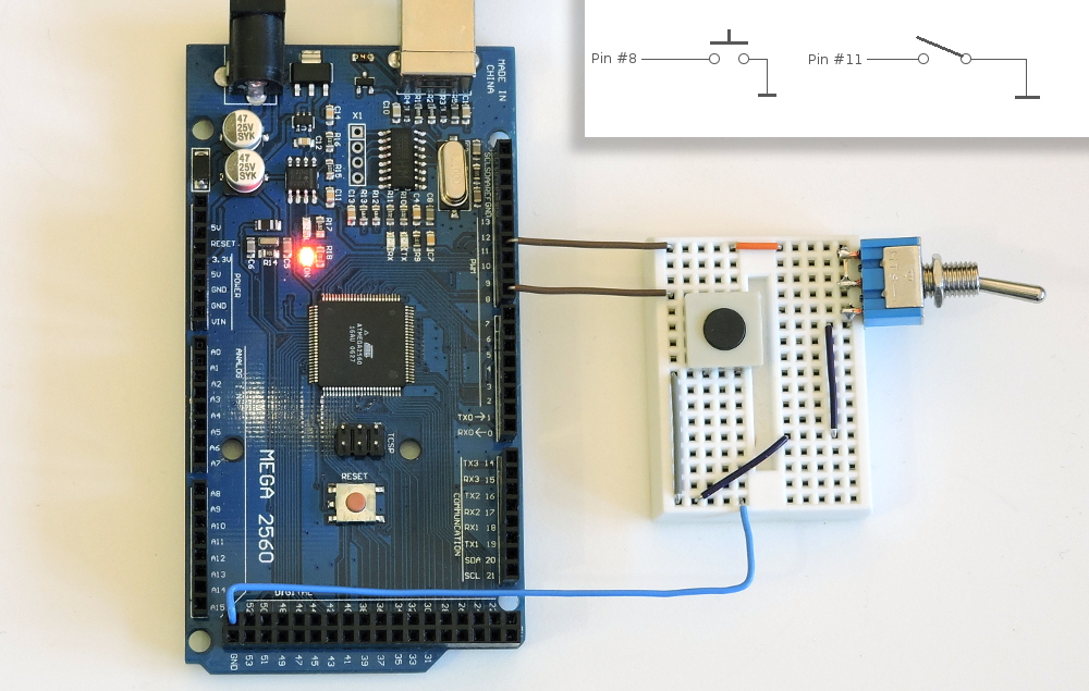
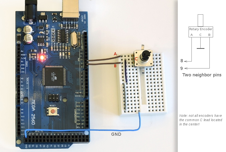
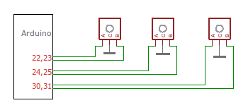
To work correctly with ArdSimX all buttons, toggle switches and encoders should be connected directly, without using any pull-up/pull-down resistors. Every switch/button occupies one Arduino pin and should have one its outputs connected to an Arduino pin (either digital or analog) and the other to the Ground. Every encoder occupies two neighbouring digital pins with common "C" on the GND:
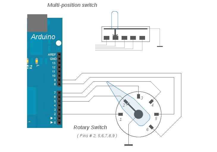
When you need to connect multi-position switch, rotary switch, you have two options for this:
1. Use several digital pins (one pin for each position) and configure all positions as "Button" inputs in configuration tool. It's simple but in this case you will need several Arduino pins (or several matrix nodes, if you use "key-matrix" extension).
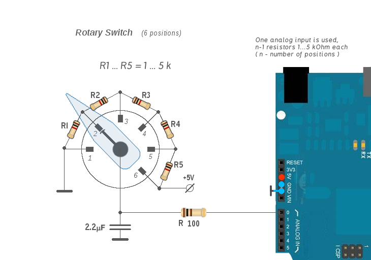
2. Use Arduino analog pin for multi-position switch. In this case one analog input is used. You will need to get a suitable rotary switch and a number of resistors soldered to this switch leads. Then use "Rotary Switch" input in the configurator to assign parameter for each position.
A common way to make an analog sensor is using a potentiometer - variable resistor connected as a voltage divider circuit. Connect the middle terminal of a potentiometer directly to analog input, and the two others - to +5v and GND. Also, various photo or Hall-effect sensors can be used instead of pots.
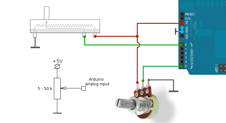
For use with Arduino you can take any potentiometer from 1k to 100k, recommended optimal is between 5 .. 20k.
Analog inputs can be used to control most of the simulator analog variables, including the 3 main axes - pitch, roll, yaw (these 3 axes may require more precise sensors), engine controls, flaps, brakes, instruments lighting, as a rotary knob for some pointer gauges (instead of encoder) etc..
NOTE: SimVimX System supports more convenient inputs extension for switches and encoders.
ArdSimX Interface supports two methods of encoder connection to Arduino that can be used simultaneously in ArdSimX - "Direct" connection and "encoder port".
Similar to the "Key_matrix" input method, the "Encoder Port" in ArdSimX serves to increase the number of encoders connected to one board. Each encoder uses one output pin of Arduino (blue on diagram). Two input pins (red on diagram) are used as bus (or "port") for reading all encoders. (You need to select two pins in configurator as "Encoders Port" before assigning encoders for bus connection).
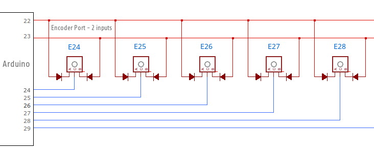
NOTE: All encoders "phase" pins (A,B) should be connected to this port strictly through diodes to exclude interference and Arduino damage!
Weigh all the "pros" and "cons" of this method before using encoders in your system. Encoder port allows you use less Arduino pins for more rotary encoders but if you have enough free pins on all connected boards, you could preferable use the direct connection method (a bit faster and no need to solder diodes).
NOTE: With new SimVimX System and one Mega2560 controller board you can make all input/output controls for your cockpit (>500 input/outpus) without matrix.
ArdSimX supports commonly used multiplexing technique known as "key-matrix". This connection method save you more pins, but it's more complicated than direct connection and needs additioanal components (lots of diodes). Several inputs ("rows") and several outputs ("columns") of the controller form a grid (matrix) .
In each intersection (node) of this grid you can place a button or toggle switch that connects one row with one column when pressed. Diodes connected in series with button are essential to prevent interference between nodes.
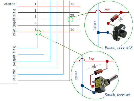
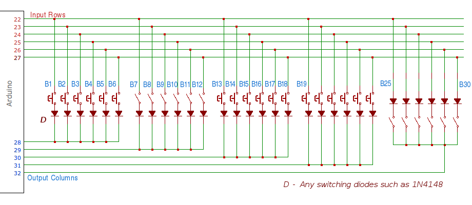
Numeration for ArdSimX configuration is shown on the diagram (matrix 6x5). Diodes can be soldered directly to each button/switch.
Pros.: Using the same number of controller pins you can have more inputs than with direct connection. N input lines and M output lines forms an NxM grid.
Cons.: More complicated wiring, more components (diodes), may need an extension boards, Since it is multiplexing method, the larger the matrix dimension the more processing time will be needed to scan all inputs, and that can affect some output devices.
Choose the minimally needed matrix size ( though, if you use Arduino board for switches/buttons inputs only, the matrix size is not critical).
To set up a key-matrix input in the Configurator you need to define which Arduino pins you will use for matrix rows and columns.
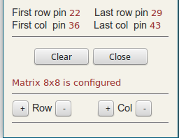
Press "Matrix inputs" button (to the left of the board picture). In the matrix dialog window you will be asked to select pins for matrix rows and columns. Select four Arduino pins one by one - the first and the last matrix row pins, then the first and the last matrix column pins.
The "Matrix Input" Tab becomes active and you can start configuring matrix inputs. You can clear matrix or change its size, adding or removing rows and columns.
Click on the "Matrix input" Tab on the right side of the screen and the matrix parameters table will be opened.
You can then click a line in this table to assign a switch/button to this node.