Incremental rotary encoders are used in the simulator interface as rotary knob controls to simulate instruments knobs mechanically geared with dials/needles, or for radio and autopilot data setting knobs, etc.
For your home cockpit you can use any cheap mechanical rotary encoders that can be found on AliExpress or Ebay. Don't look for some "special", "branded", expensive encoders., any cheap encoder ($0.3 ... $1 for a piece) works fine with SimVimX fimware. There is absolutelly no difference in work between $0.5 encoder and $30 "brand" encoder in your home cockpit!

Depending on usage in your cockpit it can be a single encoder, dual (coaxial) encoder, or encoder with built-in push-button to switch it's modes.
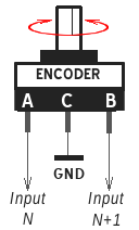
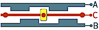
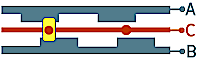
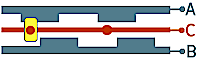
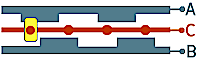
Rotary encoder has two output terminals (A,B) and one "common" C. Each output is cyclically connecting to the "common" terminal when the shaft is rotated, and the encoder generates a shifted sequence of On/Off signals on its two outputs.
This code sequence can be processed by the controller (or hardware circuit) as direction and velocity. Commonly, in relation to the simulator, we need to get the moment of state change and its direction.
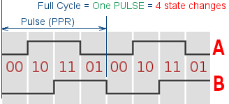
The number of phase changes in 360 degrees of rotation can vary for different encoders. For example, having 20 full phase cycles per rotation, or 20 PPR, the program can detect 80 state changes ( 80 combinations of "On" to "Off" states on A and B outputs).
Usually the encoder shaft has several fixed positions (switch effect) in full 360-deg range, that define the "touch-feel resolution" for you when you rotate the knob. An encoder may have 8 to 32 detents, and a smaller detent number may give you more sensory control when entering parameters which need fine step-by-step change. On the other hand, large number of small steps (or even complete absence of detents) is mostly usable in consumer electronic as volume regulator, etc.
NOTE: you need to know the positioning of the common ("C") terminal in each encoder, because it can be either in the middle or not for different encoders. Read more technical details about encoder types below on this page.
An encoder phase state in detent position is defined by encoder construction that may have one of the main 3 types, described below.
On the program side, within one physical "click" 1 to 4 phase changes may occur, depending on the detent type. The program should be able to detect all the phase changes between detents to determine the direction correctly, making only one step per detent to avoid excessive value change or step skipping.
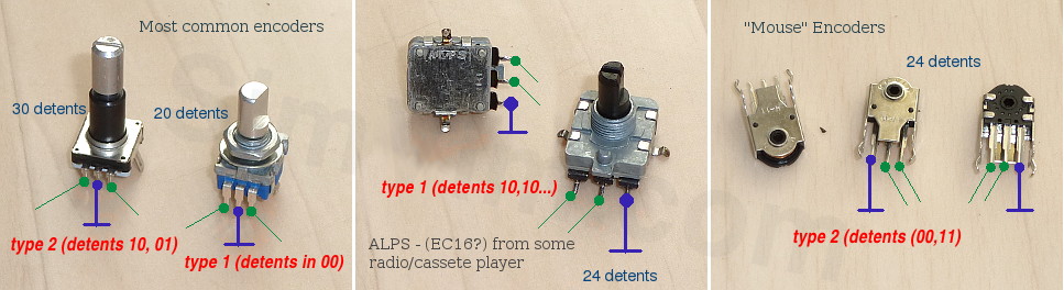
Encoder of this type has one full cycle per detent (4 phase changes), it differs in that it is always in the same phase state at each detent and when encoder is rotated by one "step", its outputs phase changes 4 times between two fixed positions what allows the program to reliably detect an encoder direction and speed.
1) All detents are in 00 state - Both A and B outputs are in the same open state.
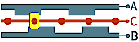
2) All detents are in 11 state - Both A and B outputs are in the same closed state.
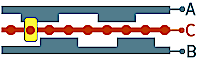
3) All detents are in 10 state (or 01) - A and B outputs are in opposite states.
Encoder of this type has a half cycle per detent, when encoder is rotated by one "step", its outputs change 2 times between two fixed positions.
1) - detents 10, 01- A and B outputs have an opposite state in one fixed position and inverted state in the next position alternately
2) - detents 00,11 - Both outputs A and B have a closed state in one fixed position and an open state in the next position alternately
Encoder with detent in each phase position (detents in 00,10,11,01), when encoder is rotated by one "step", its outputs change by one phase state and provide full resolution.
 Encoders with 1/4 cycle per detent have full resolution. For example, if an encoder has full 9 cycles per revolution (9 PPR), it can generate 36 state changes, i.e. one per each detent. Some of these encoders may not have detents at all, but they don't have tactile feedback because of it.
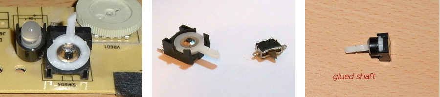
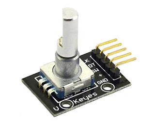
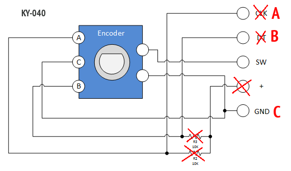
Often you can find and buy some sort of breakout board with encoder soldered in it, but it only increases the price for you. If you have bought such board, and you are going to connect it as you have read somewhere about its connection, don't do that, don't connect it to 5V! The marking (+Vcc, GND, SW, DT and CLK) on this encoder board has no practical meaning in relation to SimVim connections. All you need is only encoder itself.
Just desolder the encoder and throw away the PCB, use encoder as we described. Or, you can make changes as on the picture below:
Note: All encoders I have (a lot of encoders of different types) are very cheap and any of them can be perfectly used with SimVimX firmware, here is a link to some of them:
- Encoders with switchAs an option you can use a simplified way to emulate encoders - use two buttons or two-way switch - this will be working the same way as clicking areas of the screen in a virtual cockpit. I've made it for my transponder knobs, using two-way springed micro switches taken from old CD-ROMs.