
You can use any sensors or sources that can provide changeable voltage level in range between 0 and 5V as a signal for analog inputs, but in general, simple, common potentiometers can be perfectly used as analog sensors for most of the simulator cockpit controls. The middle terminal of a potentiometer should be connected directly to analog input, and the two others to +5v and common GND bus.
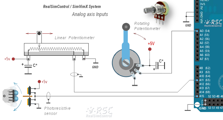
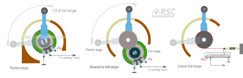
The full range of analog input is between 0 and +5v (0-100% in SimVimX ), but you may have a situation when you can't use the full range of sensor movement (e.g. when a potentiometer is fixed in place and has only a fraction of its full rotation angle used for the control lever).
The calibration function in SimVimX plugin helps you configure such sensors properly ("Calibrate analog" menu). The plugin will then convert the partial movement ranges of your analog sensors to the full value ranges.
So you can use a partial range of the sensor just fine, but you can also use a mechanical design to extend the potentiometer's travel to the full range, such as using gears or the pulley-style design shown below.
Photoresistive or magnetoresistive sensors can be used as the signal source for the analog input. It can also be any other signal source or electronic module capable of providing an adjustable voltage in the 0-5 V range with the required accuracy.
Using photoresistors is good for smooth control. First time I used this method for a DIY yoke in the late 90s using a 100k photoresistor connected to standard game port instead of a variable resistor.
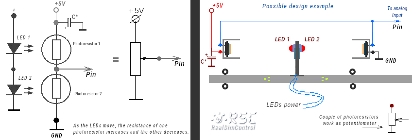
But when using the Arduino analog input, a differential pair of photoresistors is needed, connected as a voltage divider (like a potentiometer) and exposed to a light source (two opposite LEDs) that is moving toward one photocell away from another.
I've implemented this design in my Baron 58 panel.
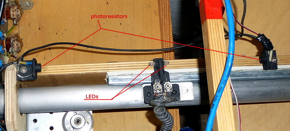
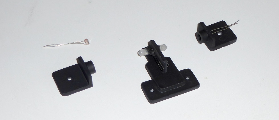
This scheme is quite tolerant to ambient light change, as the ambient light affects both resistances, keeping the proportion the same. So, external lighting variation almost doesn't influence this setup. Also, both photoresistors are placed into small "tubes" to prevent direct light influence.
You can also try different mechanics, for example rotating (tilting) LEDs as I have shown in the diagram above on this page.