
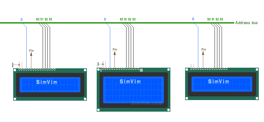
Note: We left the option of connecting LCD displays to the master board directly via the data bus. You can use any pins numbered 20 or higher. But, as most pins can be used for input multiplexers and LED drivers, you can have up to 12 LCDs on the SimVimX LCD slave board.
You need to use only 5 signal lines and GND connected to the data bus and one signal line connected to the output pin assigned for a particular display (only pins with numbers 20,21 and 30-53 can be used!). Four address/data lines S0,S1,S2,S3 should be connected to 4 data inputs of every LCD - D4,D5,D6,D7. The "D" signal of the bus is connected to the "RS" (register select) input of the LCD.

These displays typically consume little power, and you can use the +5V from the master board. To see anything on some LCD models (but not all), you'll need to add a contrast control to the input (V0) using a small potentiometer/trim (the resistance can be anywhere from 1 kOhm to 10 kOhm) connected between +5V and GND:
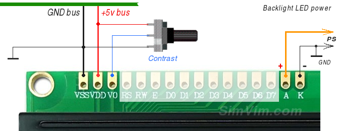
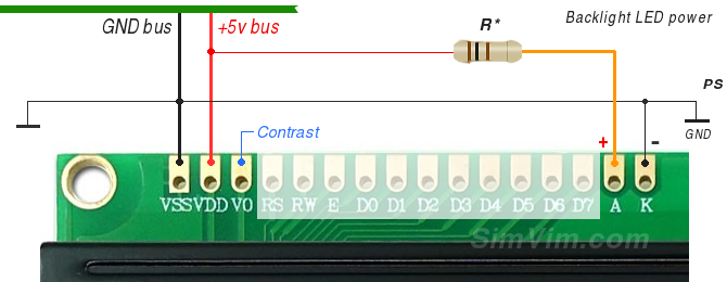
Most backlit LCD boards have 2 extra pins to power the internal LED backlight - usually pins 15(+A) and 16(-K). If you don't need to adjust brightness, just connect the (-) pin to the common ground (GND) and the (+) pin to +5V directly or through an additional resistor (to reduce and set the required brightness).
Although the backlight LEDs can consume quite much power, you can still connect the +A input to the boards +5V for a few LCDs. If you have a powerful external source for the +5v line in your system bus, use it instead of the controller board +5 output.
Also, you can use an assigned PWM output to control LCDs backlight brightness. In the SimVimX configuration tool you can assign any dataref that you will use to control the display brightness to a direct PWM output (or PWM driver output) and then connect the assigned output pin to any suitable PWM driver board, the outputs of which are connected to the backlight pins (A and K).
As example, the D4184 MOSFET module is shown below, but you can use any available module, or if you are good with electronics, you can simply use one FET with couple of resistors.
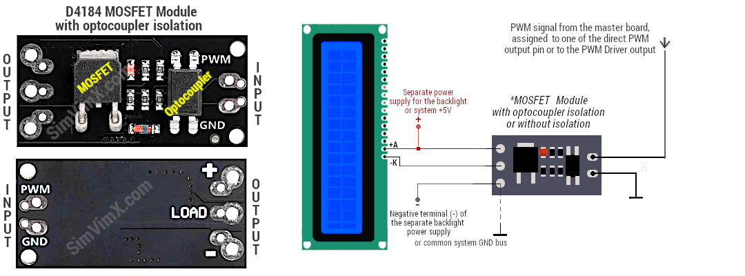
In the image above, one MOSFET module is connected to the backlight pins of one LCD, but it can also be used to control the backlight brightness of multiple LCDs (all +A/-K connected in parallel), but only if all of those displays have roughly the same backlight circuitry in terms of current consumption.