
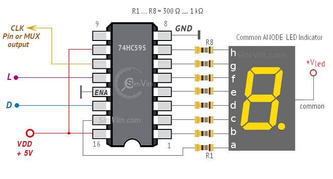
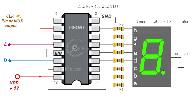
Another option is to use the 74HC595 shift registers, which was implemented in ArdSimX. The difference from LED drivers is that one HC595 chip can drive one 7-segment indicator and it needs 8 resistors for each segment to be connected. The indicators should have a common cathode.
Note: You can use 7-segment indicators with common anode as well, connect the common anode terminal to +Vled power supply and selecting the related type in the configurator.
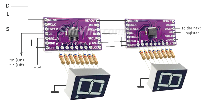
So, with a single chip, you can assemble a 1-digit display. Adding more registers to the chain, you will get a display with any number of digits. When joining several registers, you should connect together all "L" and "CLK" signals.
You can wire registers directly to the indicators or make a printed board. Another option is buying breakout boards with 74HC595 registers. You can find sample links on the "Components" page. All you need is to solder LED indicators with resistors to the board outputs.
One of the easiest ways to drive 7-segment indicators is using the same LED driver ICs as for extended digital output in SimVimX . This is convenient way to make any 7-segment display with any number of digits and digits size. With one driver you can make a 2-digit display, with two - 4-digit etc. See more details below about indicators assembled on DM13A drivers.
Trying this takes only a few minutes of your time, all you need is to take one DM13A driver or another similar IC and two 7-segment indicators. Also one constant or variable resistor 2 .. 10 kΩ is needed to set the desired brightness. Note: the indicators should have a common anode.
Thus, with a single driver, you can quickly assemble a 2-digit display, for example, for a voltage indicator. Adding more drivers to the chain, as shown in the diagram, you will get a display with any number of digits, from 2 to 8 for use with SimVimX . Each IC in the chain drives 2 digits, and the last one - either one or two, depending on your needs.
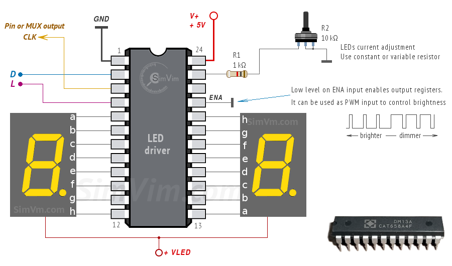
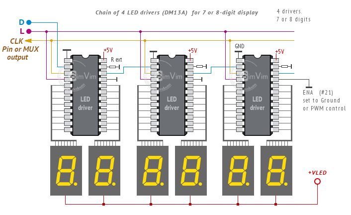
Once the display module is assembled, connect the "CLK" input to the output pin or MUX output assigned for this 7-segment display and two other signal inputs - "D" and "L" - to the common "D" and "L" output bus lines, as described on the system architecture page.
Note: You can power the driver chip from the same +5V bus as your Arduino, but you should use appropriate power supply for the 7-segment indicators (+VLED). It can be a separate power supply or the same +5V source if it is powerful enough for all devices in your system.