
Building 7 segment displays in your cockpit requires no PCB fabrication and minimal soldering, as the SimVimX System uses standard display modules as a primary option.
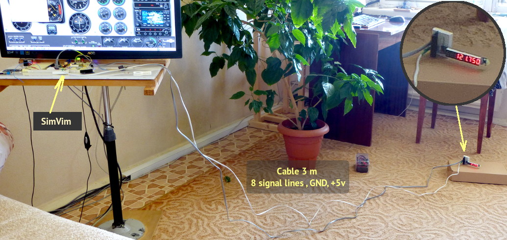
Here is a test of the SimVim multiplexer connection with a long cable to show that even at long distances and without shielding, such a system is safe from interference.
The cables used are two simple flat cables, with 6 and 4 wires, with no shielding. The cables are 3 meters in length, which is much more than you would likely have in any cockpit.
The test showed both inputs and outputs (7-segment display) work without issues.
This setup is tested with very early version of the SimVim firmware. The bus contains: 4x address + SIG + D + L . The signal EN (as the 5th address line) is separate for every output MUX and each one is using one controller pin..
GND is a common bus, that can be just a thick single-core wire (from 16 AWG to 8 AWG)
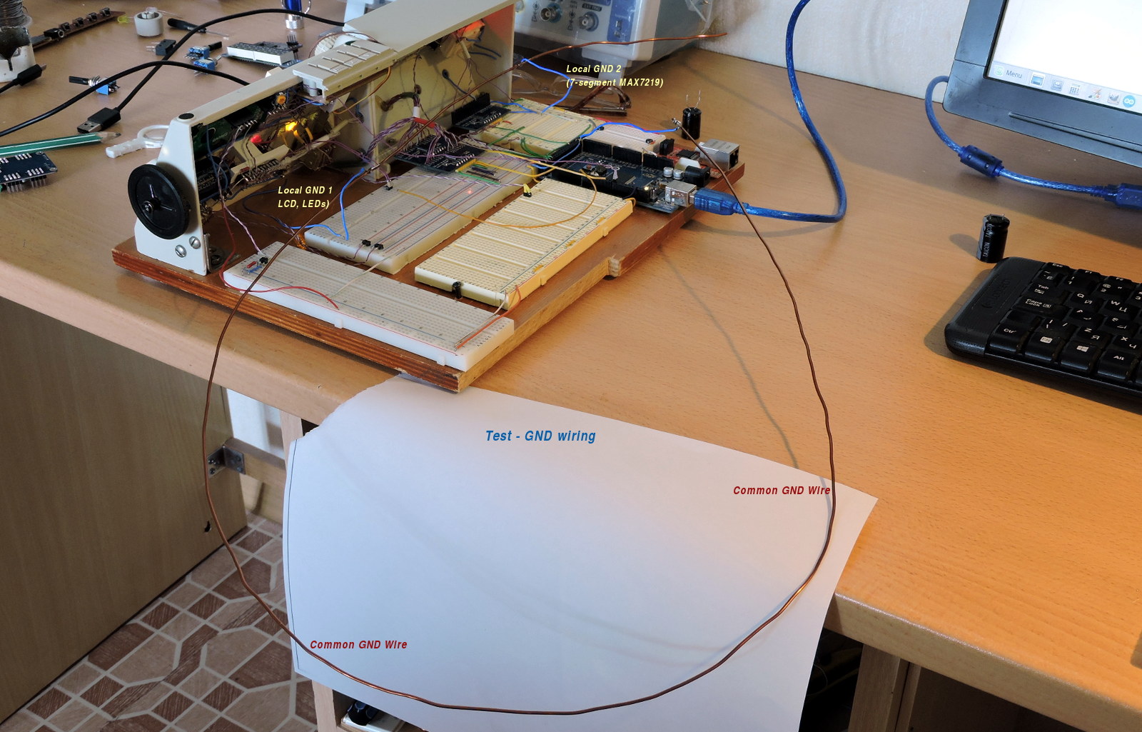
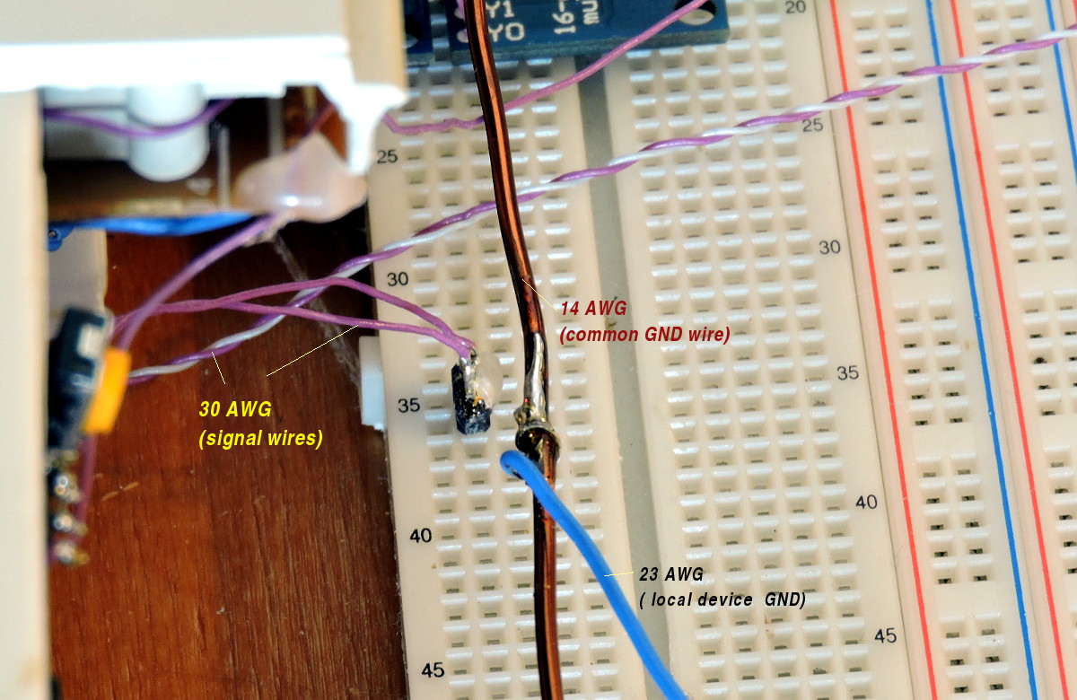
In the test setup on these photos I have used the 16AWG copper varnished wire (the varnish is removed before soldering in join spots.)

To avoid ground current loop effects and ambient electromagnetic induction, you need to follow some basic rules. As example here is the wrong and right connection options for 7-segment MAX7219 displays:
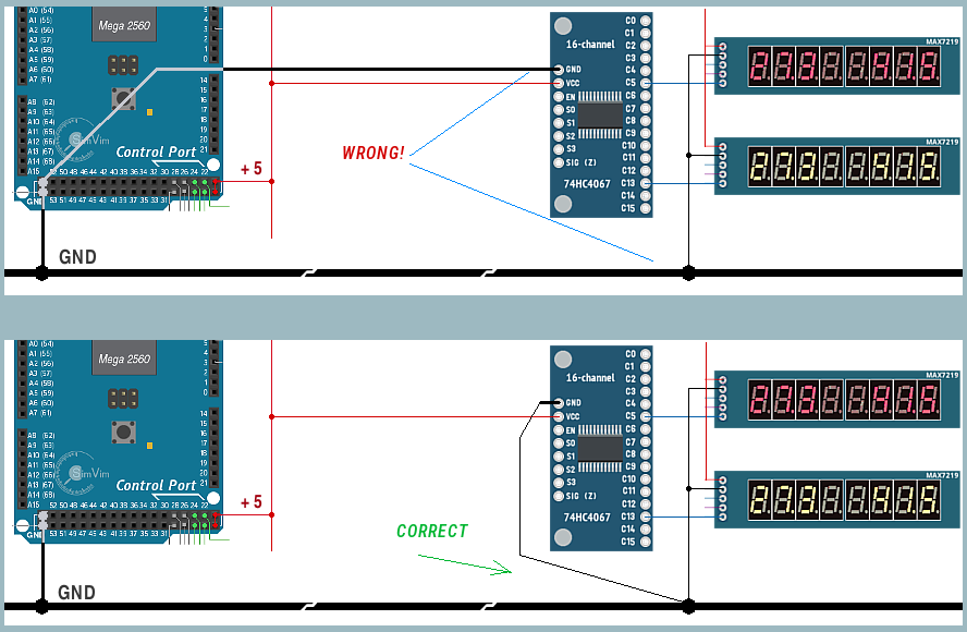
If you have some unpredictable On-Off LED states or corrupted display data, please use correct ground wiring, additional pull-down resistors for displays, pull-up resistors for input multiplexer boards and additional electrolytic capacitors, as described on related hardware pages.