Digital outputs are a simple ON/OFF type of signals that can be used to control annunciators, lights, relays, power lines, instrument flags - that is, all two-state output devices that are present in every aircraft cockpit.
Multiple LEDs can be combined into one “bargraph” indicator to display the value of a numeric parameter. You can get one of those LED bargraph indicators present on the market in different sizes, colors and sector numbers (see below on this page).
Note that some indicators in your cockpit do not require receiving any data from the simulator for their operation. Often this can be an indicator that only shows the current switch position/state (not the system state!) and can be directly controlled by this switch, as most "korry-type" push-button switches).
In the SimVimX system, from 1 to 8 74HC595 registers or from 1 to 4 DM13A LED drivers can be connected to one pin or to one MUX expansion output.
The every single LED consume quite a little power (10-50mA) itself but as you can have hundreds of LEDs in your cockpit, you must use powerfull dedicated source (+Vled +5V) for all LEDs in your system.
The amperage rate of this power supply must be sufficient to power all connected LEDs, for example, if one LED draws 20mA and you have 200 LEDs, the power supply must be rated at 4A, assuming they can all be lit at the same time.
You can use the same dedicated power supply for all 7-segment displays as well.
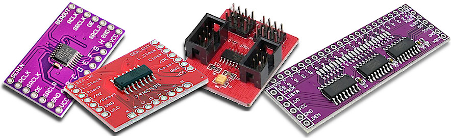
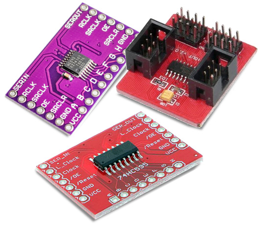
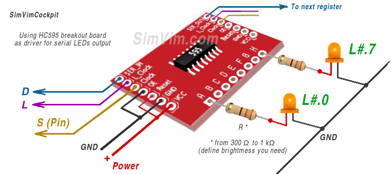
The SimVimX system uses 74HC595 registers as its primary option for controlling multiple LEDs. Buy ready-made 74HC595 expansion boards, which are available in several versions on the market.
You will also need resistors - one for each LED, connected in series to the board outputs.
In addition, any of these boards can be used for seven-segment indicators.
This DM13A LED driver is used in SimVimX System to provide multiple digital outputs (16 LEDs, relay, etc. for one driver). This IC is a register with a latch for 16 constant current LED outputs. Other similar drivers can be used too.
All driver ICs listed below are similar in functionality and pin mapping, so you can use any of them that are easier to get for you.
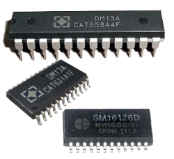
Some of these ICs have DIP casing (DM13A, DM134, ST2221C), others may have SOP24 casing. But this is not a problem, using them is not so difficult with the cheap SOP28 adapter.
The main method for driving large numbers of LEDs in SimVimX is the "series-parallel shift" method using latched shift registers.
The easiest option is to buy multiple breakout boards with 74HC595 registers. All you have to do is solder the LEDs with resistors to the boards.
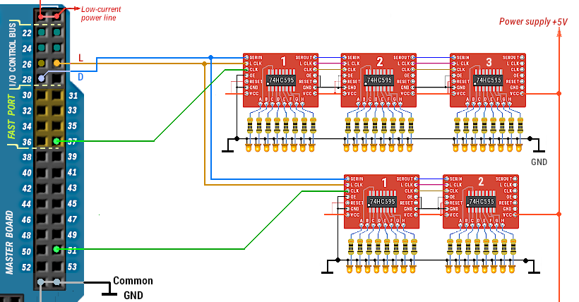
You can use from 1 to 8 registers connected in series, that allows you to have up to 64 LEDs on ONE output pin.
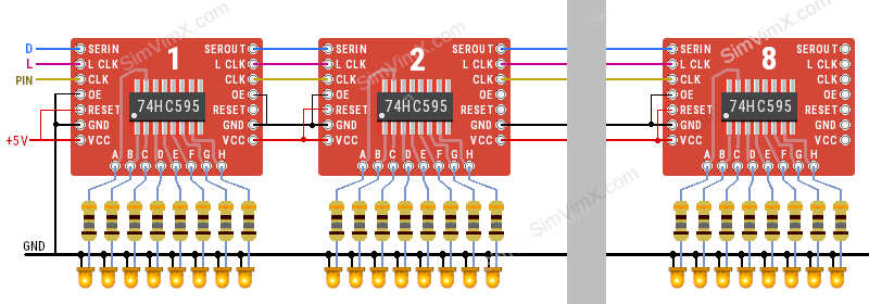
In the example below two pins #37 and #51 are used to control two register chains:
NOTE: Resistor values can range from 300 ohms to 1 kohms - you may want to start with a higher value to decide if the LED brightness meets your needs.
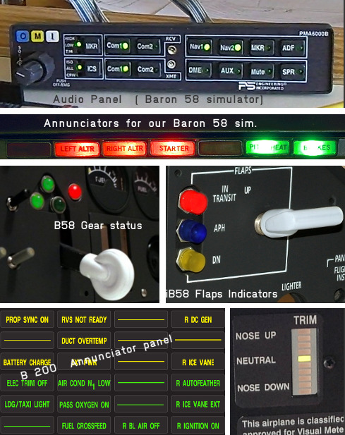
For example, when I built my Baron 58 panel (using the earlier ArdSim I/O interdace), all the LEDs in the audio panel had 1k ohm resistors, and the LEDs were more than bright enough:
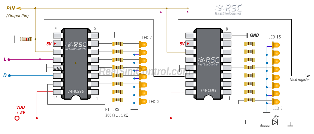
If you have a lot of 74HC595 register chips in your electronics stash, you can use them by wiring LEDs directly to the registers, make your own PCB or use SOP adapters. Here is the connection diagram:
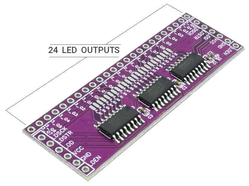
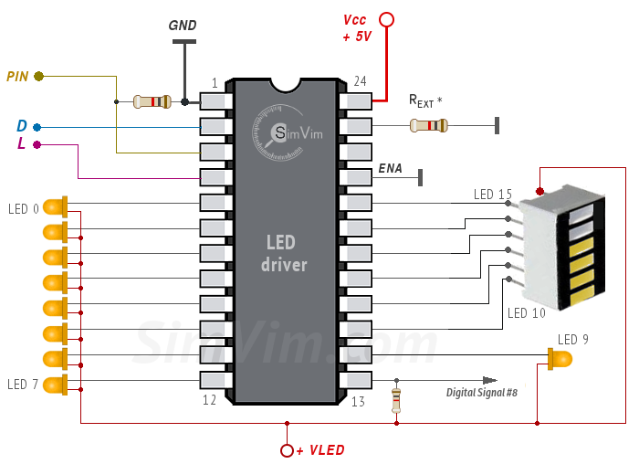
An option for driving multiple LEDs in a SimVimX system is to use constant current LED driver ICs such as the DM13A and similar, which are the same latch shift registers as the 74HC595 but have 16 outputs, use a common anode connection for the LEDs, and do not require resistors for each LED.
You need to connect common GND, 3 signal lines - two common "D/L" lines and one control signal "PIN" connected to the assigned pin or multiplexer output. The driver chip itself can be powered using +5V output pin located on the master board or the same dedicated power source (+Vled +5V) used for all LEDs (in this case don't connect VDD to the +5v pin on your Arduino!):
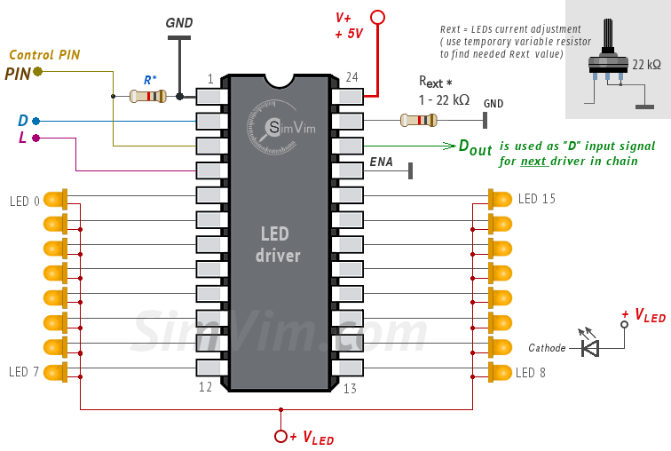
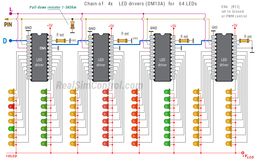
The LED operating current is set with one reference resistor connected to the Rext input (terminal #23), that can have resistance between 1 ... 22 kΩ and defines the current (and brightness) for all LEDs. You can connect a variable resistor to adjust the current as needed and then replace it by a constant resistor.
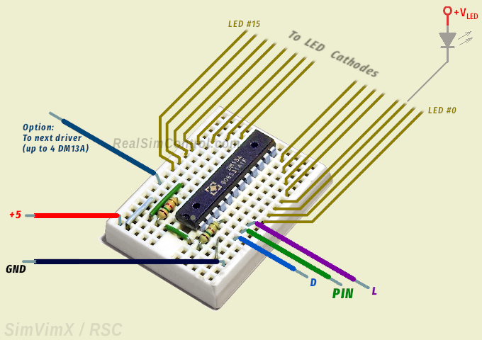
I didn't find any ready-made expansion boards with such LED drivers but you don't necessarily need them. You can use a bare DM13A chip inserted into the small "breadboard" that can be taped to any part of your cockpit, or simply glued near to the group of LEDs ( see an example).
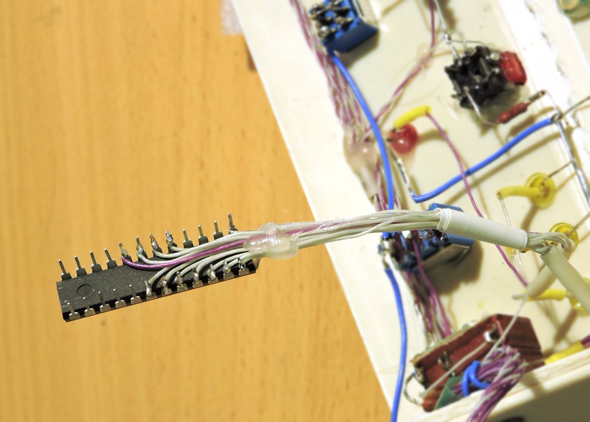
Also, using DM13A drivers in DIP casing, you can solder thin wires directly to the driver pins. Then this driver can be attached to the surface near the LED group using thermo-glue or 2-side duct tape.
See more tips about wiring your cockpit on the "Wiring" page.
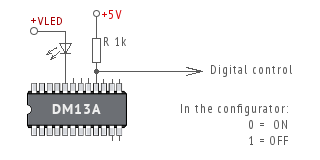
Same as for direct outputs, you can use a serial output as "On/Off" control signal for other circuits, relays, MOSFETs, etc.
For this, instead of LED, use a pull-up resistor 1k connected to +5v bus and use this terminal as output pin for digital control. In the picture you can see that output terminal #16 is used as digital output (all others can be used either for LEDs or digital outputs as well).
You can connect several Serial LED register chains to the output multiplexer, which can be used for 7-segment displays at the same time.
In the example below pin #42 is used for the Output MUX and its pin #15 is used to control the register chain:
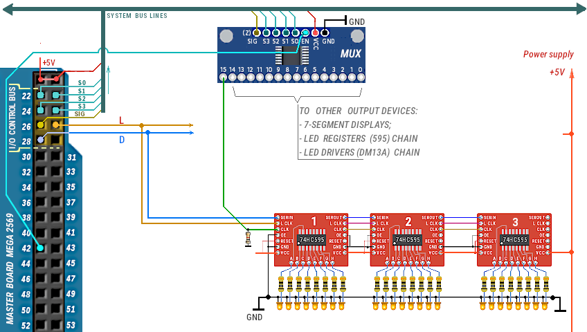
In the plugin configurator, open the connected output multiplexer, then select the LED driver type (595 registers, DM13A Driver or LED Matrix) and click an empty multiplexer output (as #15 in the example above).
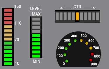
To display some parameter value as a linear or circle graph indicator you can use either series of individual LEDs arranged in the shape you need (circle or line) or ready-made LED bar graphs.
When assigning the LEDs you need to choose the "LED Bar Indicator" option in the plugin configuration window, select only the output number to which the first LED will be connected and insert the number of LEDs (sectors) your indicator includes.
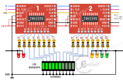
The number of LEDs (sectors) in your indicator is limited only by the number of registers or drivers in the chain.In the first diagram, a 10-sector LED bar is connected to HC595 register chain outputs #2–11, and the remaining outputs are used for individual LEDs. The second diagram shows a 6-sector LED bar connected to LED driver outputs #10–15, and driver output #8 is used as a digital control signal for some other electronic circuits:
Note: The LED bar display modules with built-in voltage-controlled driver (like LM3914N) can not be used with digital outputs - you need to use PWM-controlled output for such displays instead.
SimVimX supports using the MAX7219 driver to drive up to 64 LEDs, but this can be more complex for the user since all the LEDs in your panel need to be connected in a matrix of 8 rows and 8 columns. The MAX7219 is the same driver used for 7-segment displays with 8 characters and 64 segments, but in the case of 64 LEDs, a lot of wiring is required.
It is not "Serial LED output" - all diodes are connected as matrix or "grid". To make using LEDs with MAX7219 easier, you can buy one of the MAX7219 dot matrix module (example link), which also is very convenient for testing purposes because it has detachable LED dot-matrix module. To test all your assigned annunciators you can use this dot matrix and then detach it and connect two rows of wires (anodes, cathodes) that go to your LEDs connected as matrix grid.
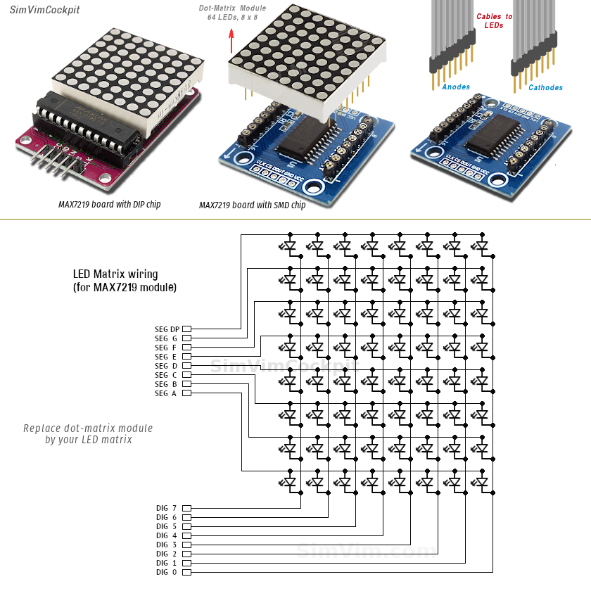
First, you need to "connect" the Matrix Max7219 driver in the configuration window, either to pins #30-37 or to one the Output MUX pin, selecting the "LED MATRIX" extension type
Then you can assign LEDs and datarefs for them as usual.
If you need to control the LEDs brightness, link the assigned LED matrix module with one of the brightness knob in the configurator, just like for 7-segment indicators with software-controlled brightness.
If you only need to add a few LEDs, either permanently or temporarily for testing, you can simply connect the LEDs (or other digital devices) directly to the output pins of the Mega2560 board, taking into account some limitations described below. A single Mega2560 pin can be configured as digital output to control one LED.
When controlling the "On/Off" type of output device directly with controller pins all you should worry about is its power consumption. According to AVR tech spec, the maximum ("damage") current for a single pin in output mode starts with 40 mA, that is quite enough to drive most LEDs used as indicators. Likewise, any other directly connected device (actuator, integrated circuit, relays, etc) should sink the current no more than 20-40 mA.
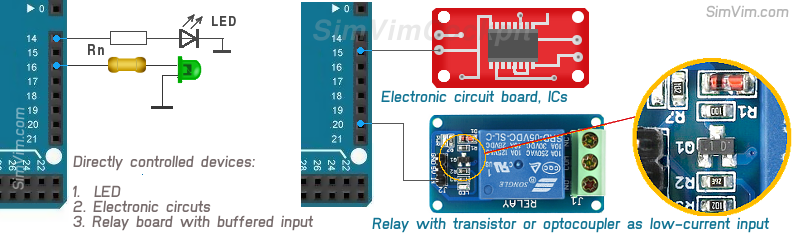
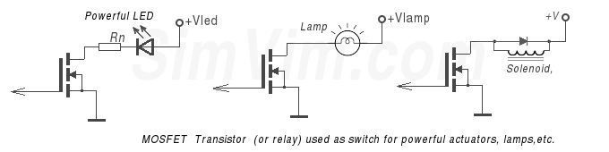
Powerful output devices that have high-voltage or high-current consumption cannot be controlled directly from microcontroller pins, you should always use some kind of buffer circuit for such devices.
This can be a PNP transistor, a MOSFET or a relay. If you use a relay, make sure that it has buffered input itself (as mentioned above) or it's a low current relay having a coil with higher resistance: