
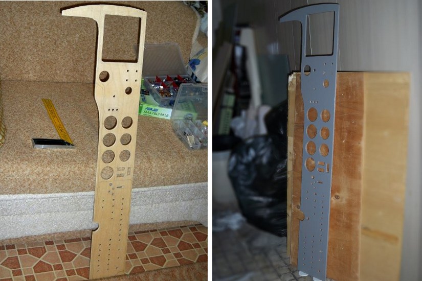
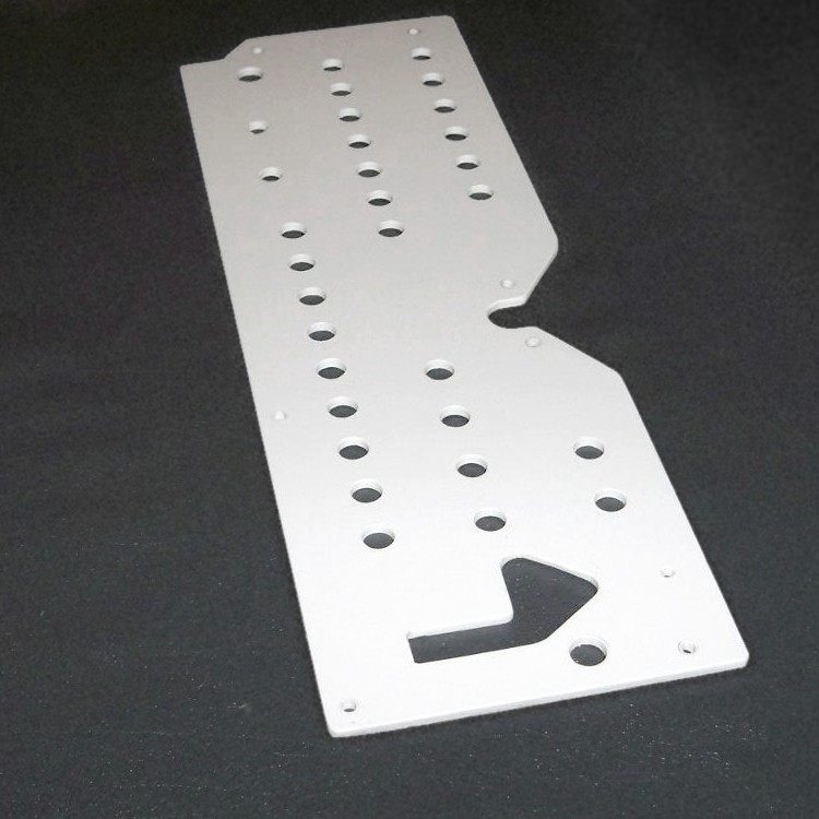
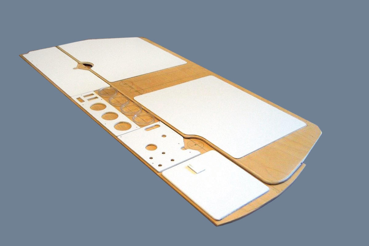
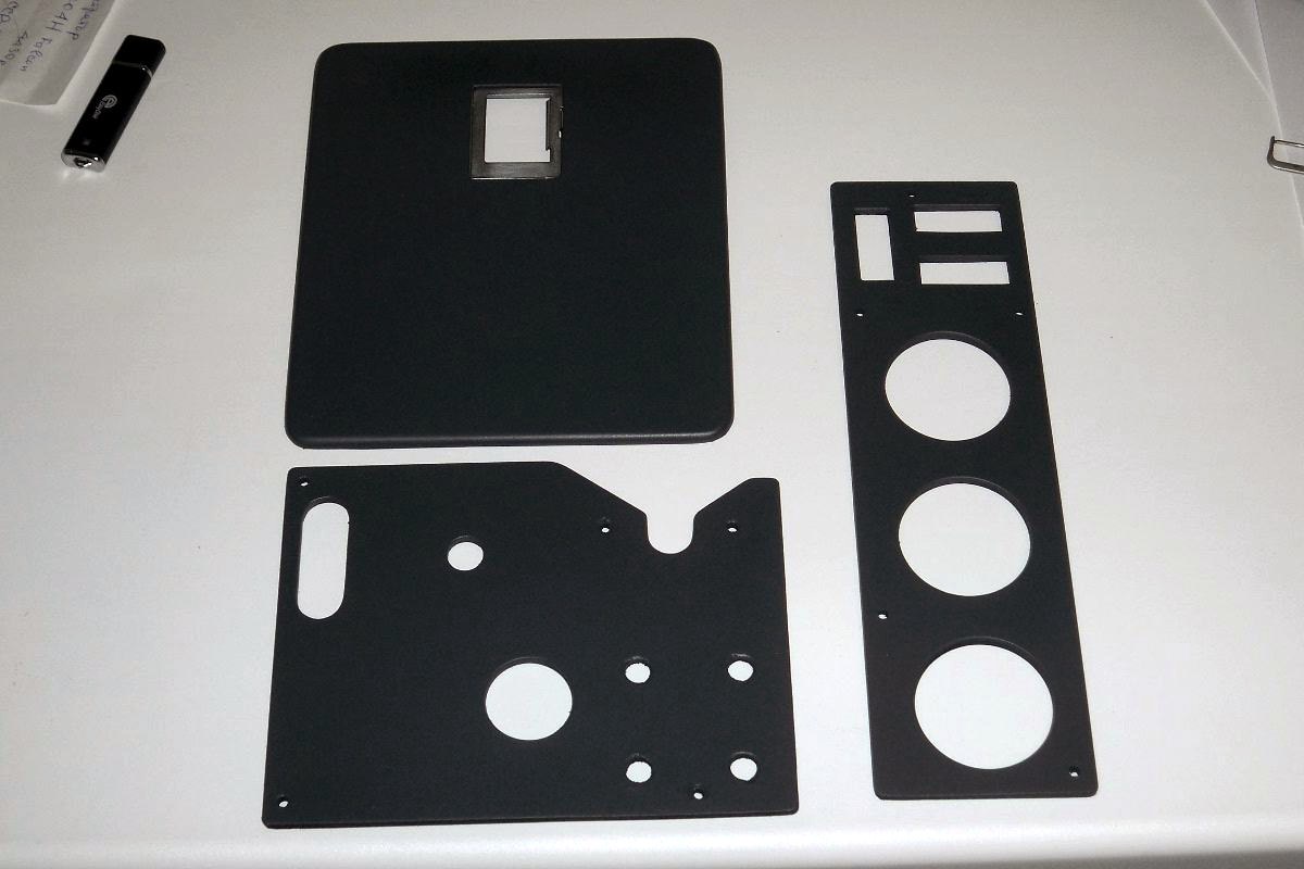
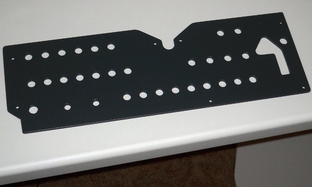
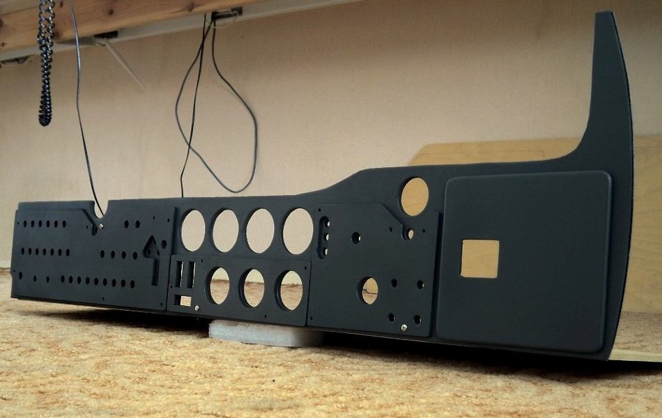
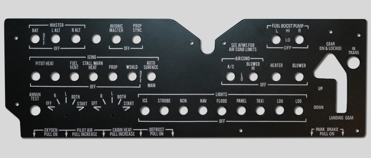
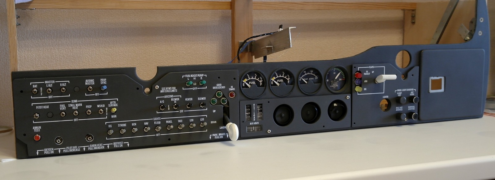
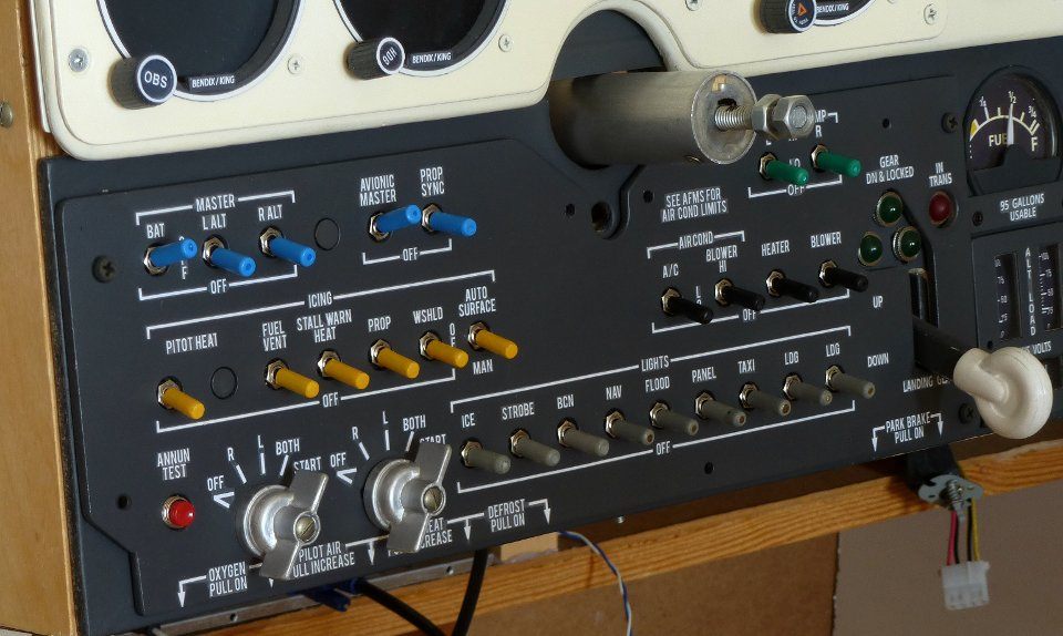
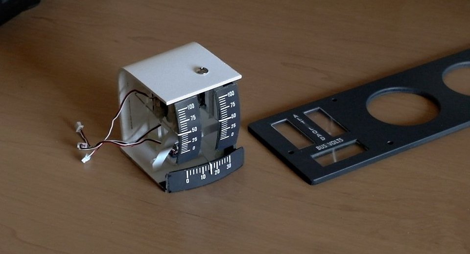
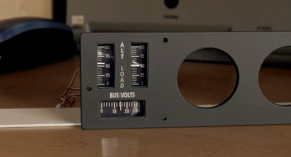
The lower control panel is made of 5mm plywood. After cutting the holes the panel has been sanded and painted with primer then with spray paint. Sheets of 4mm PVC were used for the cover plates of the switches, vent and ammeters, for flaps panel cover and for the door of the "glovebox".
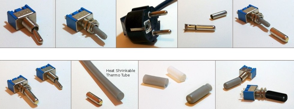
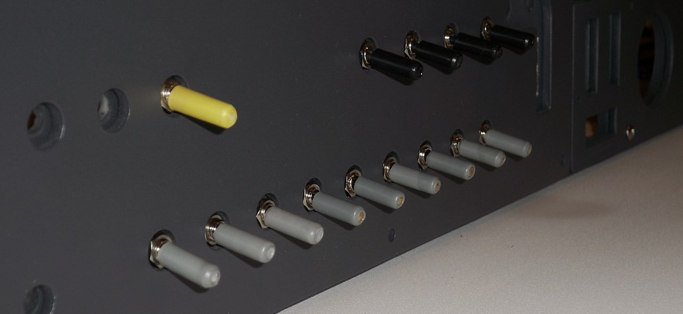
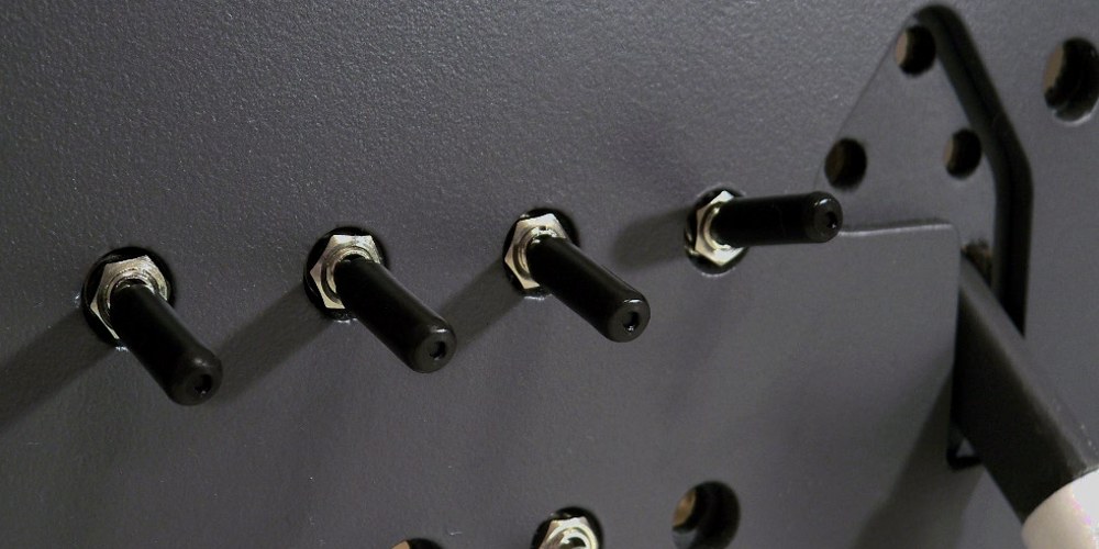
Whilst I haven't got switches with a suitable size arm, I've made them from scrap materials (tubes, colored heat shrinkable tubes).
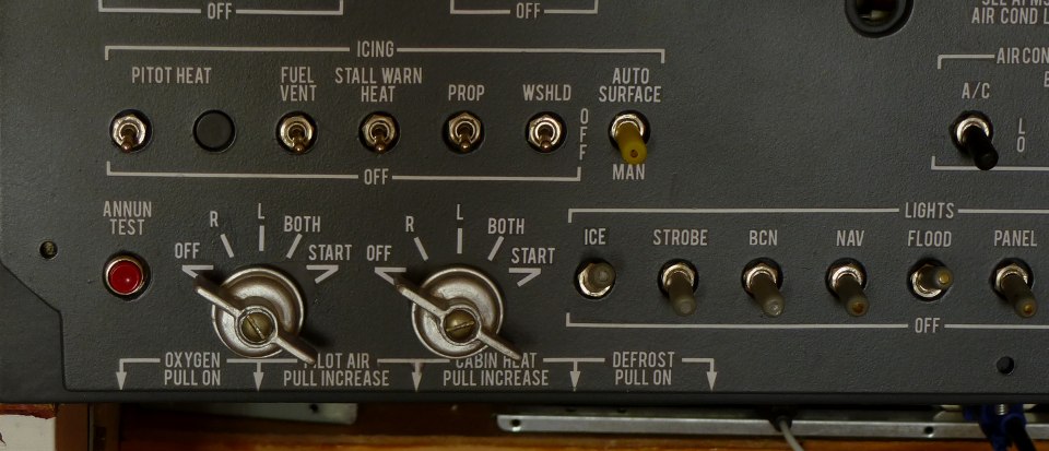
All lettering on the panel was printed on selfadhesive paper, but I very carefully choose the color of lettering background to fit with panel color, and cut the paper closest to the letters. It's not a "long living" lettering, though looks good enough and easy to repair.
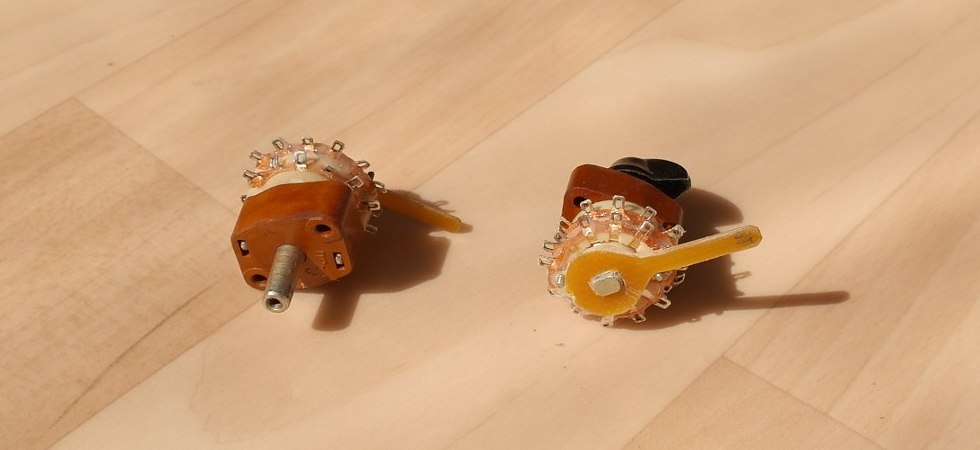
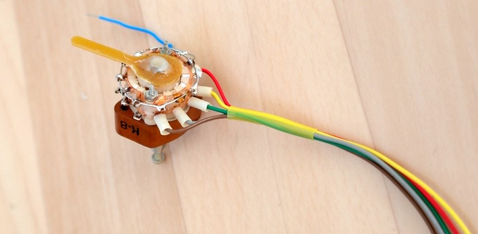
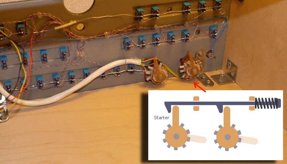
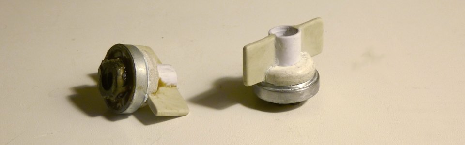
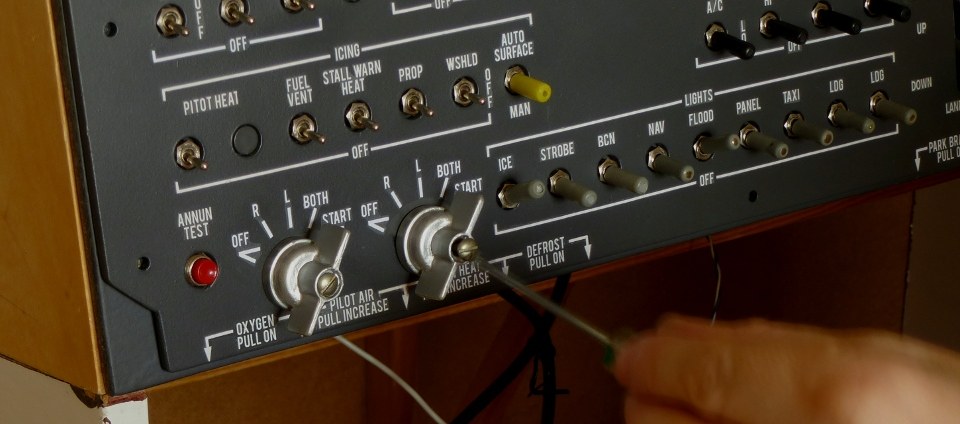
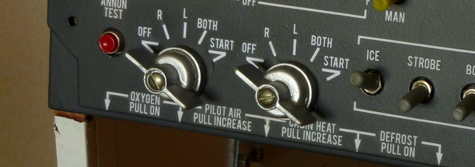
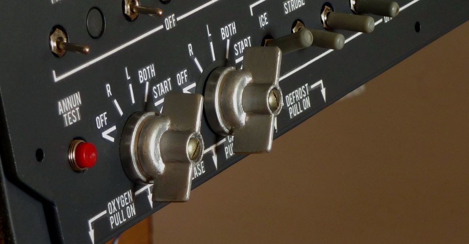
Two 5-position rotary switches used as starters/alternators switches. 1-st position is OFF, then 3 positions for the left, right and both alternators choice.
Last position for starter not fixed and the handle is returning back with spring lever.
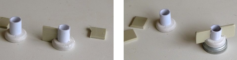
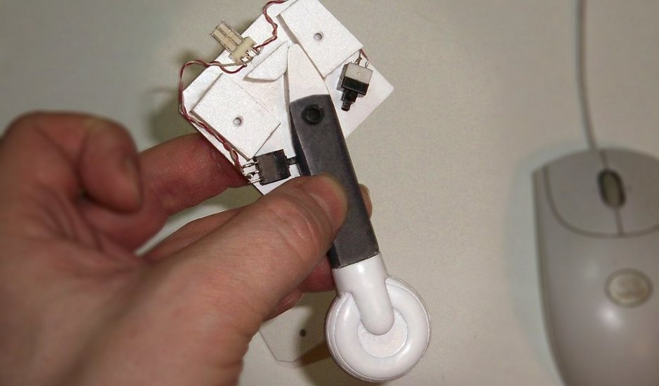
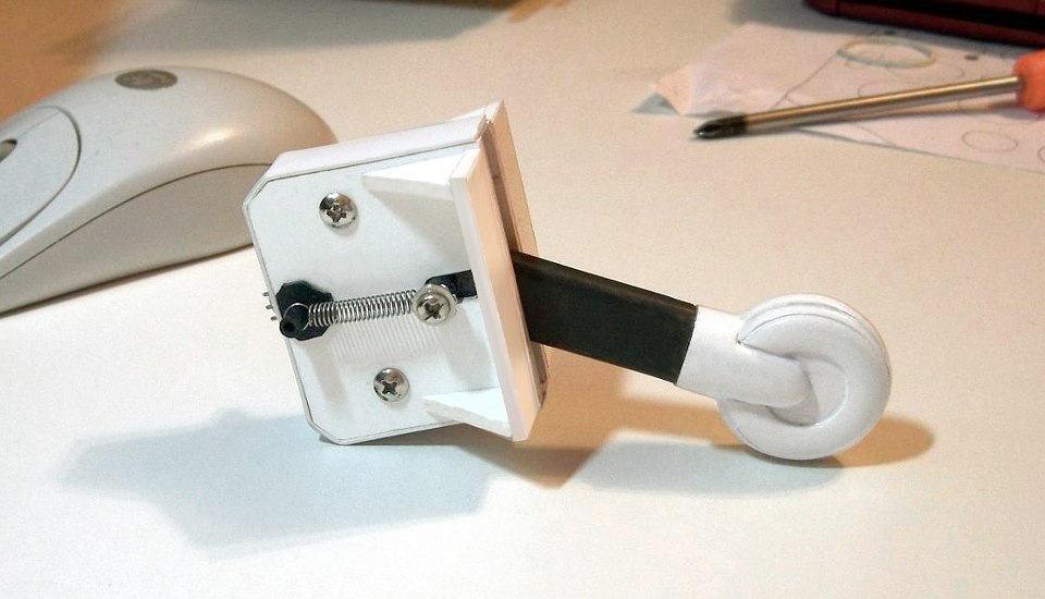
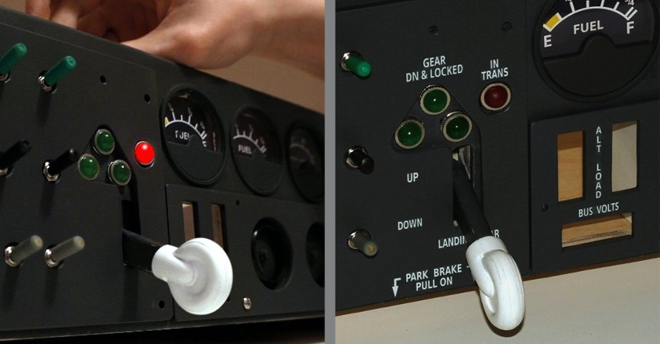
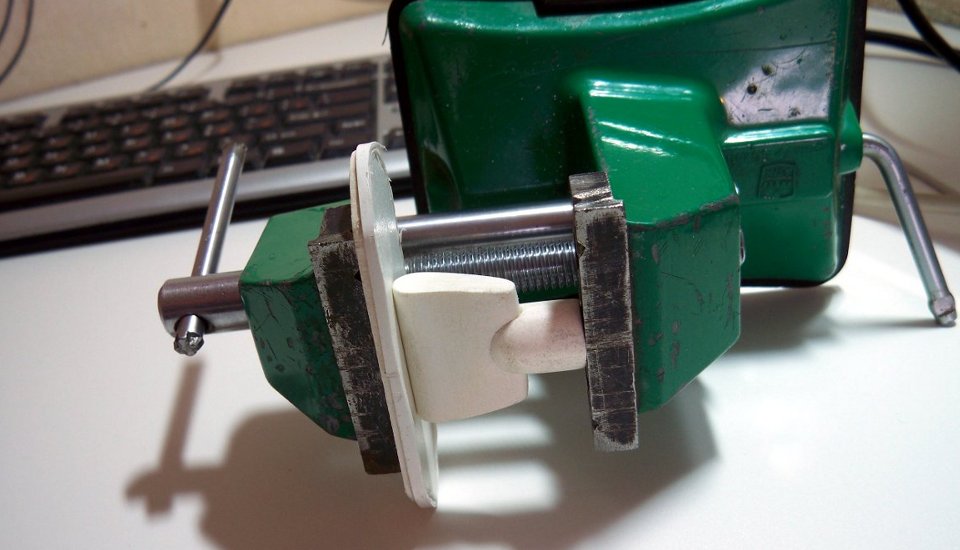
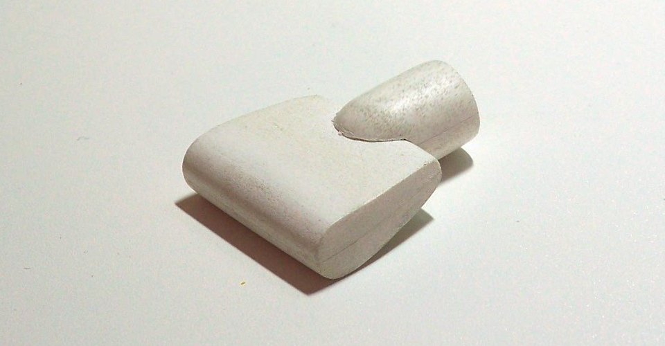
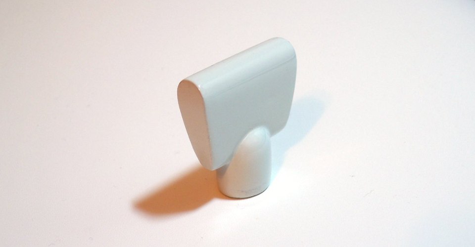
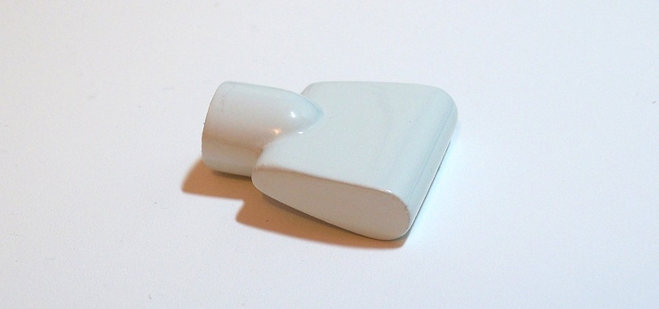
Landing gear lever is made of 8mm PVC (Photo 1.2). To give the desired "wheel" shape on the sides are glued 2-5 mm plastic pads (photo 3):
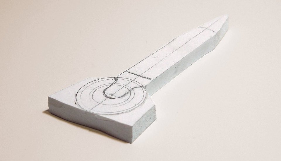
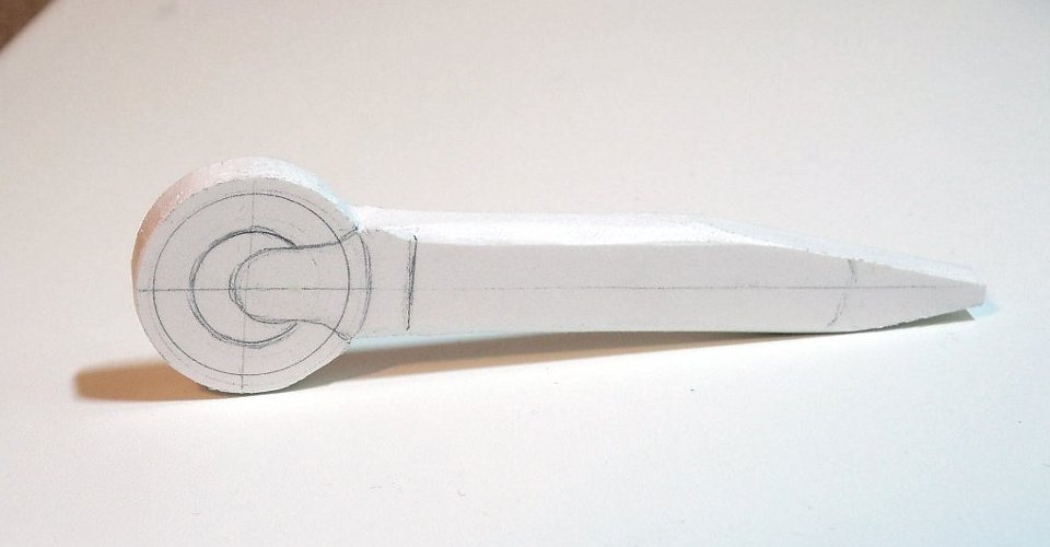
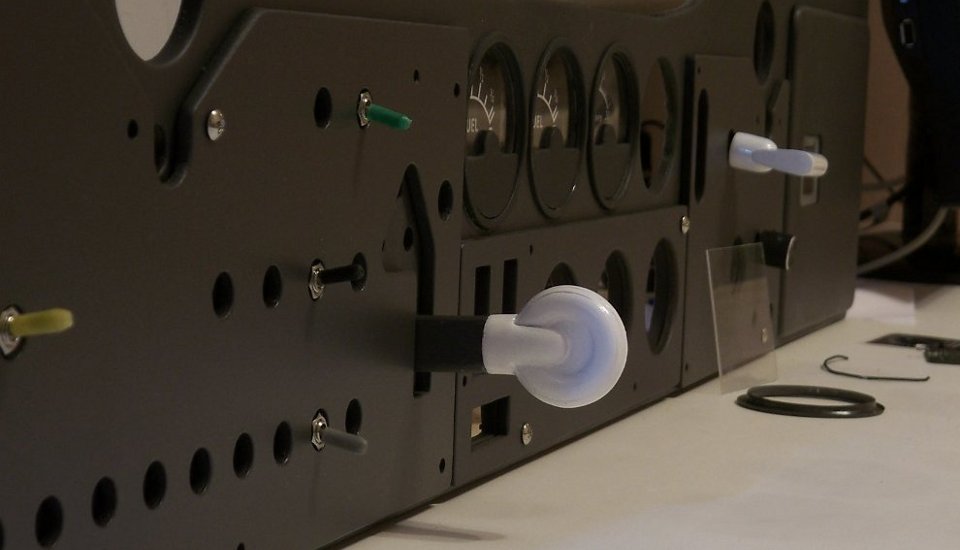

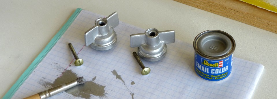
The lever sanded to the final form of (4), then spray painted (white-40 King Spray and dark gray MOTiP № -4075):
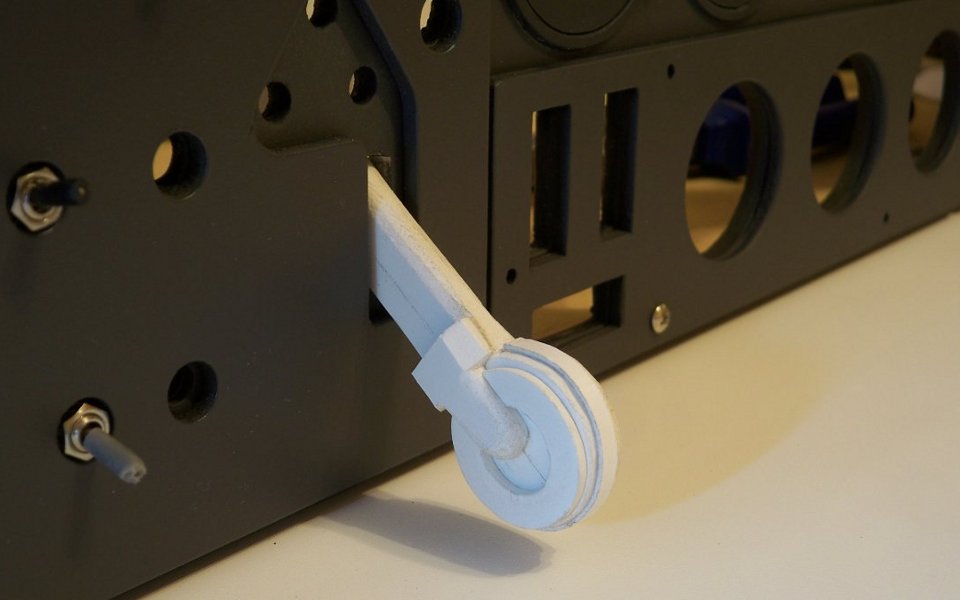
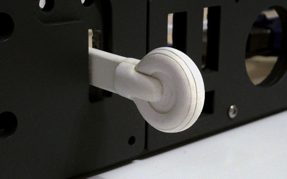
A locking mechanism of the end positions and the housing are made of 8mm and 3mm plates. Locking is provided by two springs, the video shows the running. The whole structure can be done-metal of course, while this version also shows enough strength and durability.
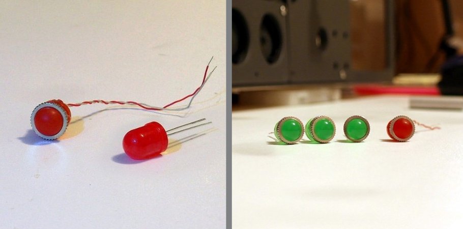
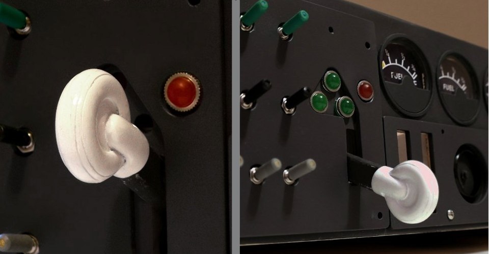
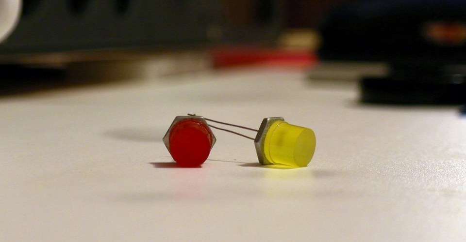
For indicators the green and red 10 mm LEDs are used. Preheated suitable size round nuts are fixed on the LEDs. Then they glued into the base panel.
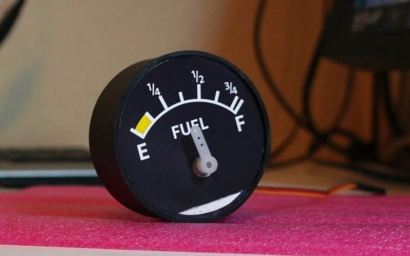
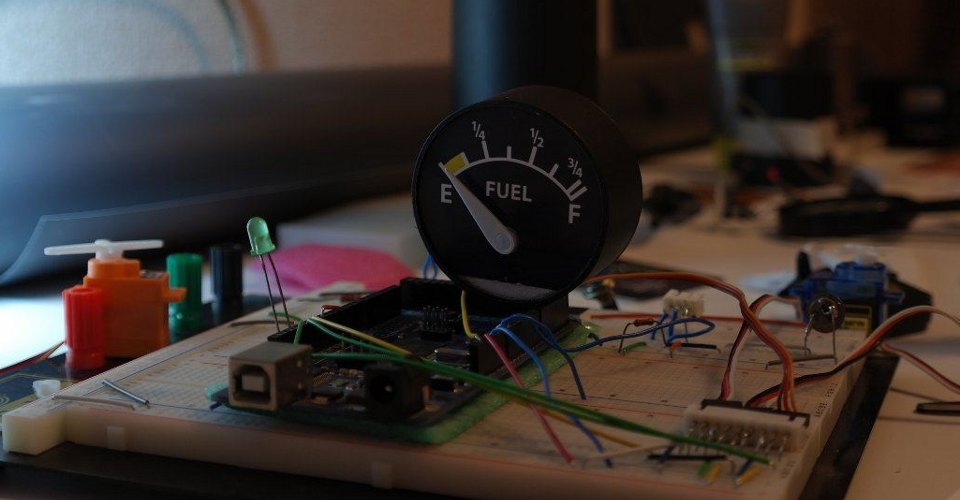
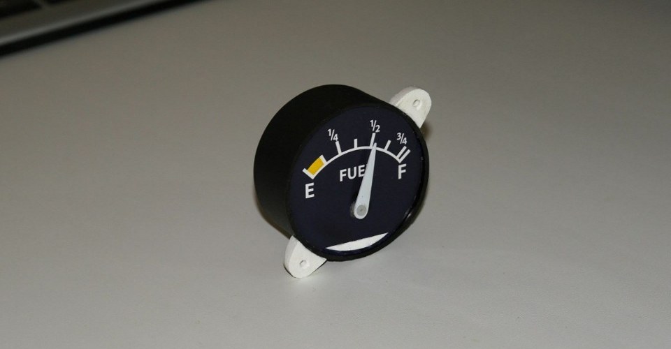
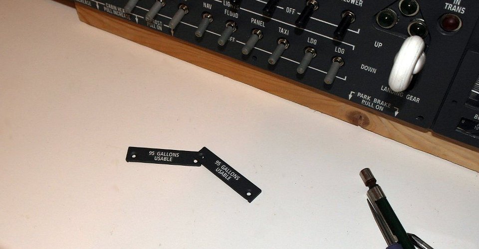
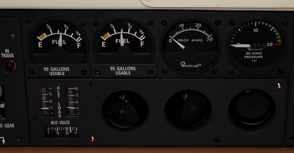
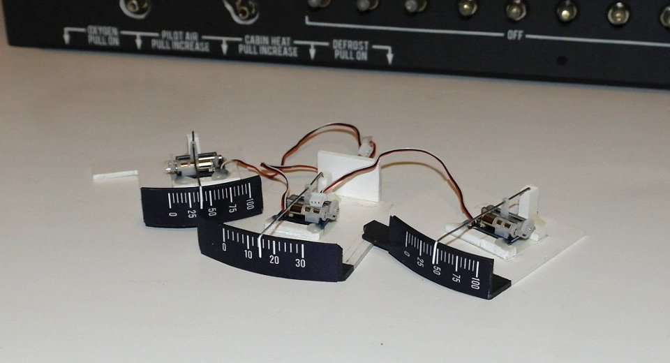
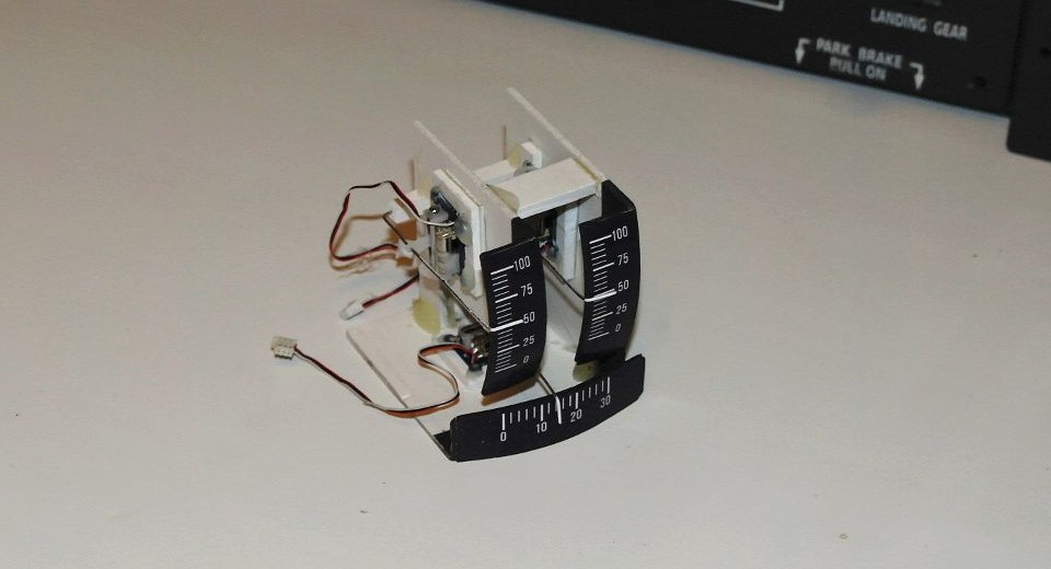
For the fuel gauges are used - a segments of PVC pipe, disks of 2mm PVC for faceplates, printed dials and the servos. The Arduino program, receiving data from a group DATA #62 (1, 2), converts them to the angle of rotation. Mini servos was purchased on E-bay or in HobbyKing - (Sub-Micro Servo )

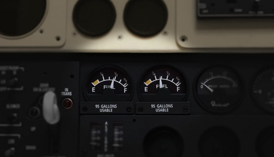
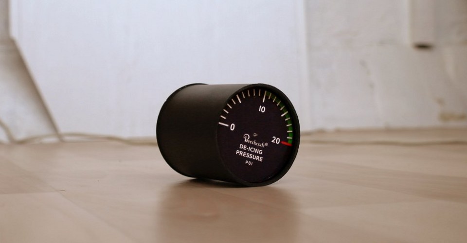
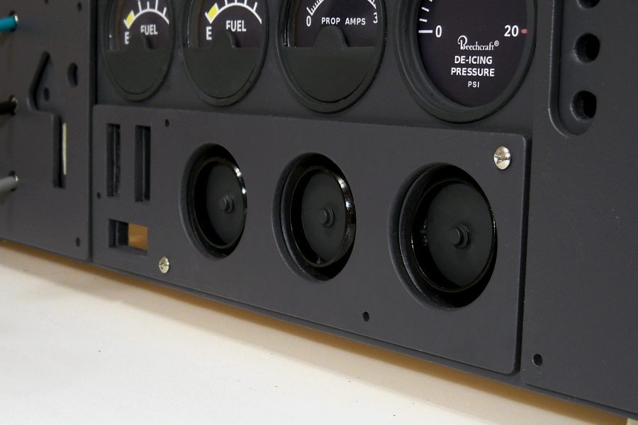
PropAmps (amperage in the system heating the blades) and De-icing pressure (pressure in the de-icing system) gauges show only two values: 0 when the corresponding switches are in the off position and nominal values when they are turned on and the electric system is on.
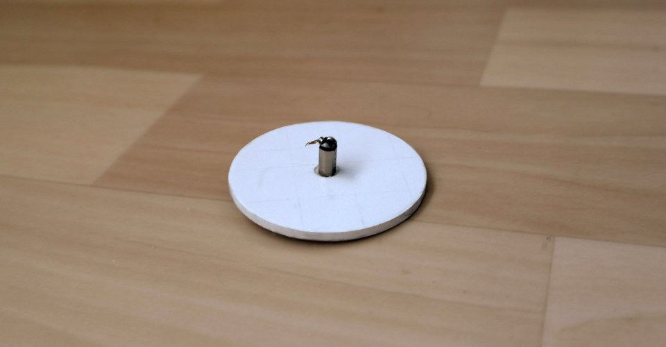
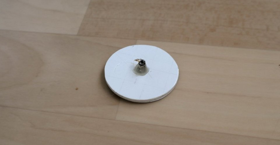
For these gauges the same materials was used, and pager micromotors for actuators . To these motors via a control circuit Arduino sends a single short pulses to flip the needle in either position (end positions are defined by limiters).
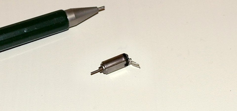
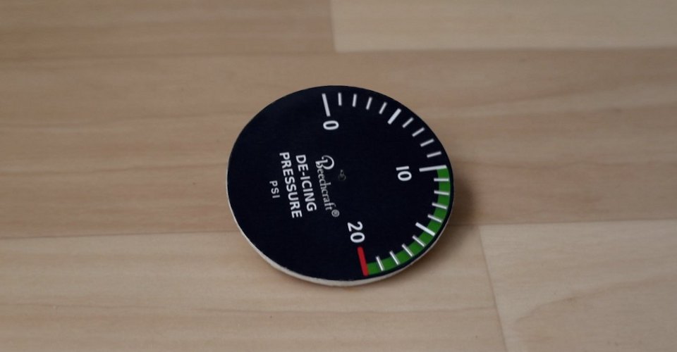
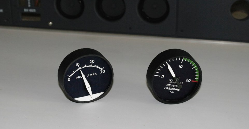
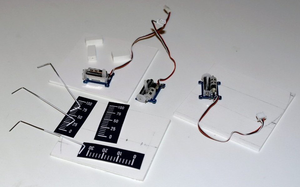
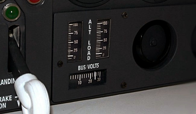
For this type of instruments analogue indicators of suitable size are generally used (on the left picture). I did not find these nearby, and the ones that I have seen online - industrial indicators cost $20-40. It was much cheaper and faster to buy a linear micro servo at HobbyKing - (HobbyKing Ultra Micro Servo 1.7g). Besides, with Arduino it is very easy to control them.
Working stroke of this servo is not sufficient for direct needle driving, so the simple construction had to be made to increase the stroke. The design is simple, but reliable, the work took a couple of hours. All the details can be seen on photos below.
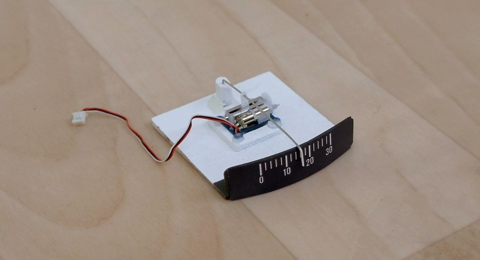
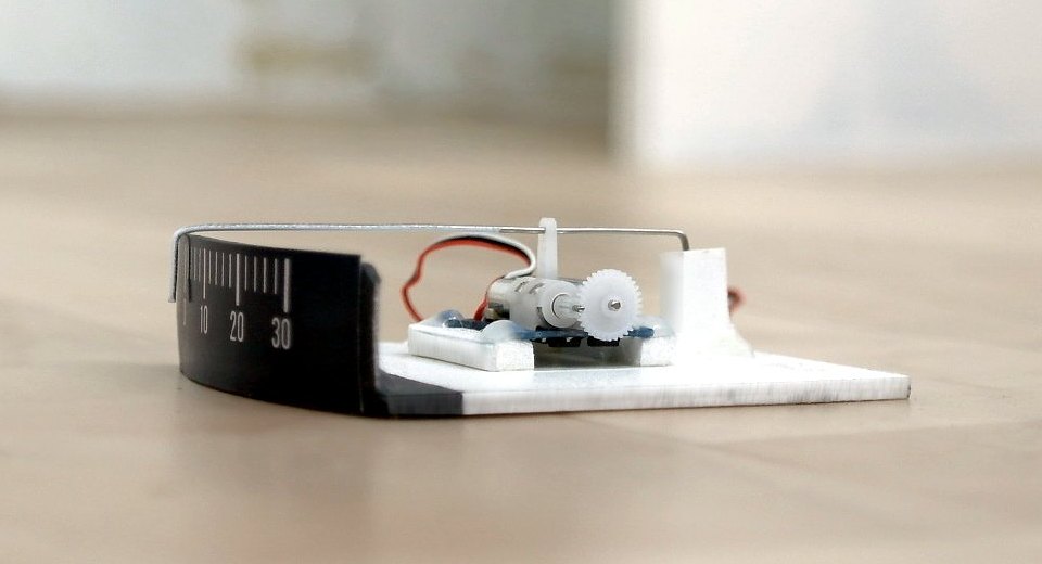

On the video - test connection to Arduino to set limits of pointer movement.
The servo makes some noise when position of the pointer is changed rapidly, while with slow motion - it almost silent.
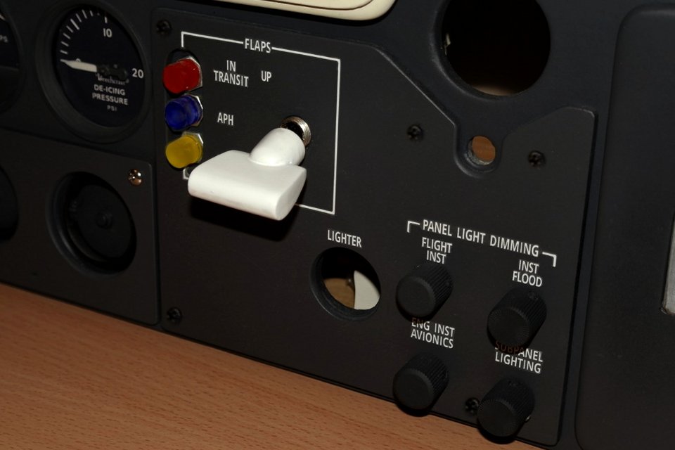
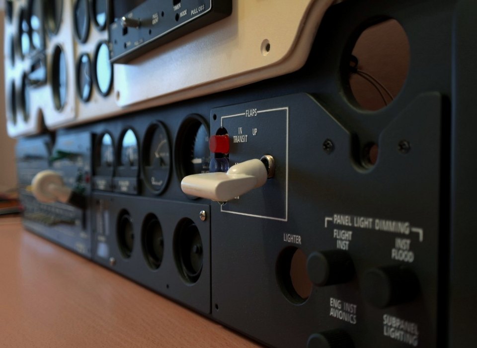
Flaps control handle is glued from 5 mm and 8 mm PVC and painted with white spray. A three-way toggle switch is used as an input device.
Indicator lamps are made of 10-mm diffused LEDs , the tips of which are cut flat and polished. Nuts from the toggle switches of suitable size are fastened to the bottom side of the LED.
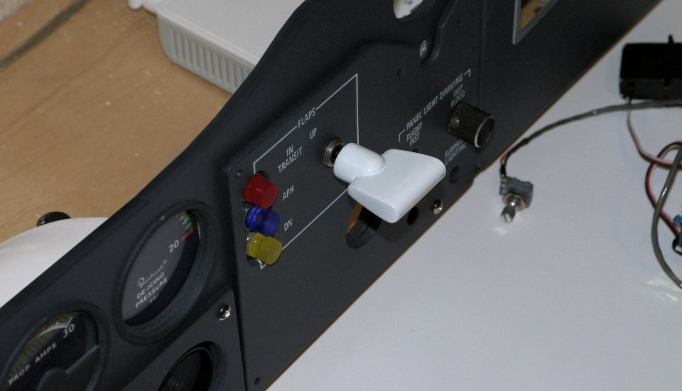
The lighting control section is 4 resistors with knobs. Two of them (left) are connected to the Arduino for the instruments illumination control. Two others are intended to adjust the panel lighting (Flood) and control the bottom panel lighting (Subpanel lighting).
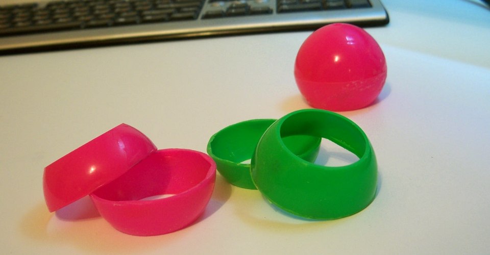
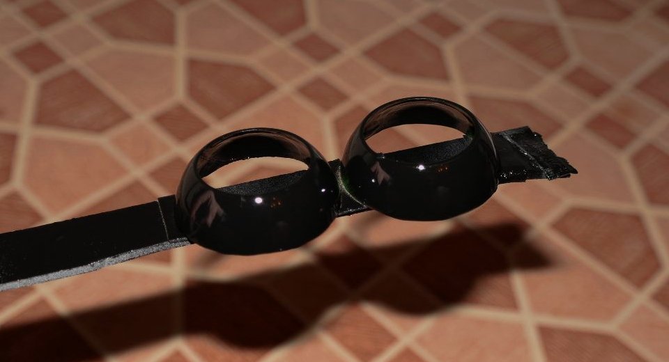
To produce the elements of ventilation the plastic balls of suitable diameter are used. The inner rotary shutter is made from 2-mm PVC with transistor cap glued in the middle and the metal axle on the back side.
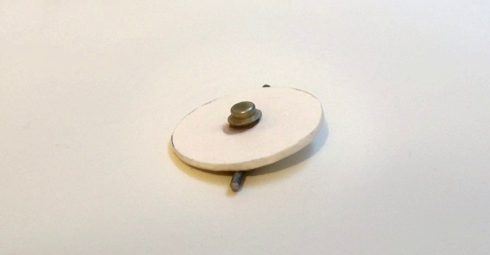
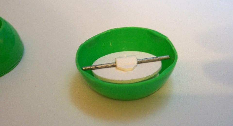
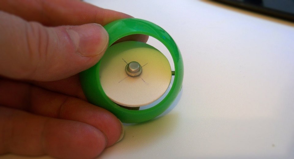

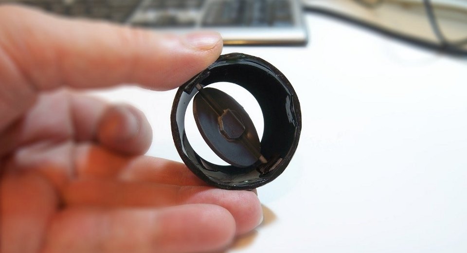
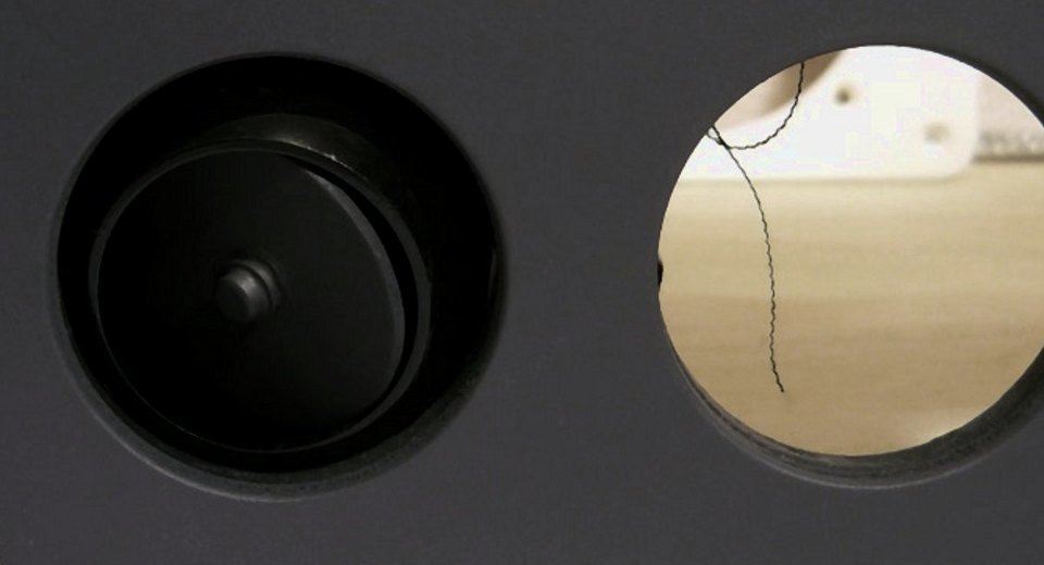
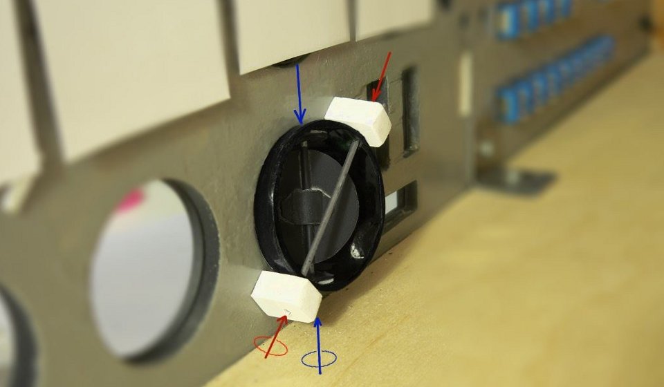
Shutter axis is fixed by pair of PVC pieces with cutouts for the pins. The second axis goes at a 45 deg. to the first through the shell and mounted in the two racks on the basis.
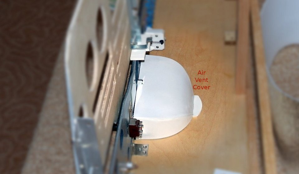
Although at first it was not planned, but with this design begs the question - why not to make the ventilation "working"? It will take only one hour of time.
The result - the hood that covers the whole construction - and under it in the hole at the bottom of the case is 90 mm fan to drive the airflow from below.