The numeric indicators used in real airplanes can be replicated in your home cockpit using 7-segment LED modules, which can be a pretty realistic substitute, especially if you can find indicators with the right size and color.
The term "7-segment" is related to the form of displaying numeric information, and does not define the type of the display itself, its construction and operation. There are many display types (LED, LCD, Gas, Incandescent, etc.) that use 7 segments to display numbers, as well as 9, 14 and 16 segments for alphanumeric symbols.
Using 7-segment LED indicators in home cockpit is an easy way to simulate various devices displaying decimal numbers. In real planes some displays are made using such LED indicators.
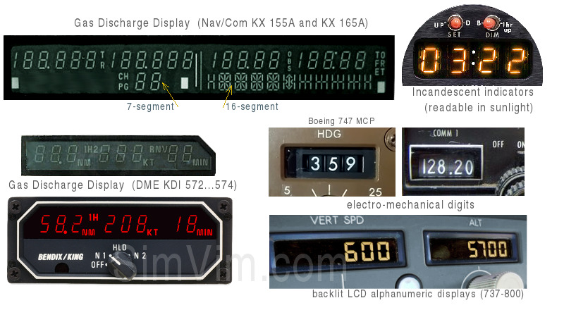
However, most real equipment (especially older ones) may rather have Gas Discharge displays (as in most of Bendix King equipment), Fluorescent display modules, Incandescent indicators, and even electro-mechanically controlled numeric displays.
Since all these types of displays (except the mechanical ones) form digits using a 7-segment matrix, some of them can be reproduced using LED indicators of suitable size and color.
In newer equipment all these indicators are often replaced with LCD displays that have fixed 7-segment sectors or with LCD matrix displays.
SimVimX firmware directly supports the most commonly used 7-segment display modules based on the MAX7219, TM1637 and HC595 shift registers, as well as custom displays built on 16-bit LED drivers (DM13A) or shift registers (HC595). You can connect as many indicators of different types and sizes as you need to have in your cockpit. It depends on the connection methods used - an output multiplexer, direct connection or combined.
Display types:
Each connected display can consist of up to 8 digits and be used to output 2 or 3 parameters simultaneously, when one parameter value's position is shifted relative to the other.
Connect output multiplexer board as described below, to 4 address lines (S0-S3), SIG line (S) and output control pin assigned in the configurator for this output MUX.
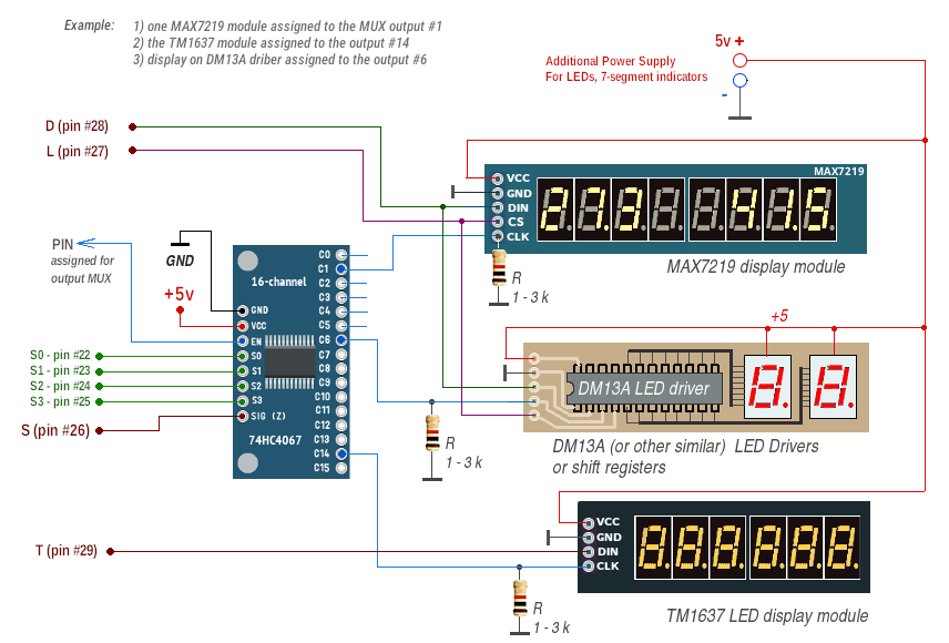
1. Each display module build on MAX7219 driver has 3 input control signal (besides power lines) - CLK, DIN ("D") and CS ("L").
The CLK input is connected to one of 16 multiplexer otputs, with number that you have assigned in the configurator (0-15).
Two other signal inputs - "DIN" and "CS" - should be connected to the corresponding common signal lines - "D" (pin #28) and "L" (pin #27) output signals.
2. Display based on the DM13A LED drivers or shift registers has the same connections as for the MAX7219 driver listed above.
3. Display module build on TM1637 driver has 2 input control signal (besides power lines) - CLK and DIO . The "CLK" input is connected to assigned multiplexer otput, the "DIO" input is connected to the "T" signal line (pin #29), not to "D" line!
So, you can use one multiplexer to connect up to 16 displays. The same way you can use the 74HC595 shift registers instead of LED drivers (but drivers are preferred)
NOTE: the "pull-down" resistor ( ~1...3 kΩ) connected to the CLK is used to prevent the LEDs from being randomly lit or because of interference between different displays connected to one multiplexer (because while multiplexer output is not selected it remains in high-impendance state and without resistor the display input connected to it is very sensitive to interference from surrounding signals.
To extend number of 7-segment displays or serial LEDs annunciators that are located in some part of your cockpit, but you don't need more than 8 outputs, you can use 8-channel 74HC4051 multiplexer breakout board.
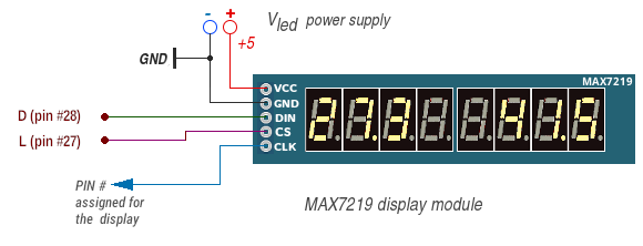
In case when you need to use only a few 7-segment displays in your cockpit, or you need to add one more to assigned multiplexed ones, you can use "direct" connection, without multiplexer. The "CLK" input in this case should be connected to assigned controller pin (no need to use a pull-down resistor), other signal inputs (L,D) are the common for all output devices (pins #27,28).
Note: for direct connection only 8 pins from # 30 to # 37 of the controller board can be used (this is Port C directly controlled, for speed reason). You can assign them in the configurator, all other pins are not available for direct display control.
Here is the wiring diagram for MAX7219 and TM1637. The difference is that the TM1637 module only has a "DIN" input, which is connected to the "T" signal line. In the example diagram you can see how 2 Max7219 and 2 TM1637 are connected directly (pins #33,34 and 36,37 are assigned as control signals for each display), the same applies to LED driver/register based displays:
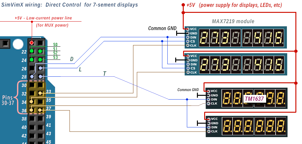
Please note: the "daisy-chain" connection for the MAX7219 modules is not supported. Instead, you can connect up to 16 displays to one single output pin using one output multiplexer as described here.
The configuration is unified for all displays, you'll only need to select display type and some additional options. All listed parameters are pre-configured for output in the correct format, with dot position, number of digits and some of the display options pre-defined.
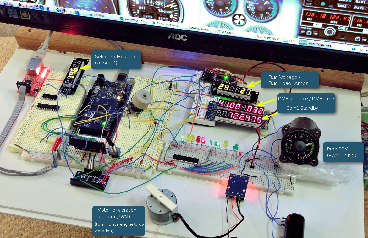
Any display can be easily configured to output more than one data value. For example, you can have 2 or 3 independent data on one 8-digit display. In the picture above you can see Bus Voltage + Bus Load on the right TM1637 display and DME distance + DME time on the upper MAX7219 display).
To display data value in the position other then the display right side, use the "Position" option, which allow you to shift least significant digit to the left. Just enter needed offset value.
To output additional parameter value on the same display, you need to select second parameter, then select the same display output pin number as for the first parameter was assigned (use the "Apeernd" button), and then enter shift position number.
You can configure 7-segment indicator to display some custom text (as fixed text or text displayed by conditions) using these 26 symbols (along with digits and dot):
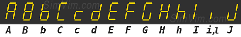

Note: this option is available since ver. 0.9.17 beta.
The text can be a part of the displayed parameter value, configured as shifted text and displayed alongside with parameter value or, it can appear in the same position, replacing the value by condition.
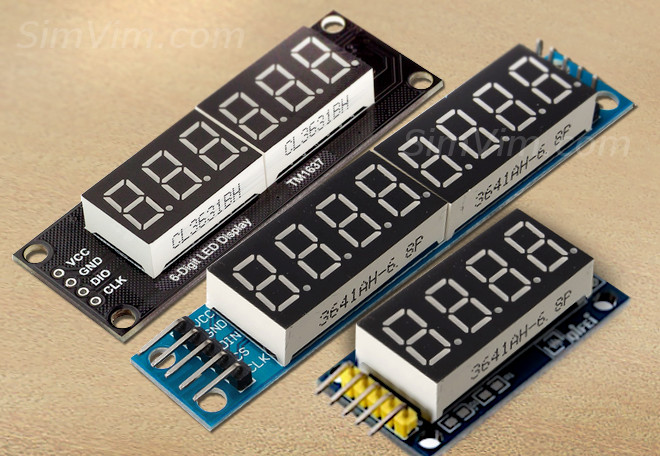
There are various pre-assembled modules on the market, with MAX7219 or TM1637 drivers, or modules with 74HC595 registers.
Usually, the MAX7219 module has 8-digits (sometimes 6) and TM1637 has 6 or 4 digits that allow you to quickly make any needed indicator for your panel - you just need to connect the display module as described here and configure what to display on it and how.
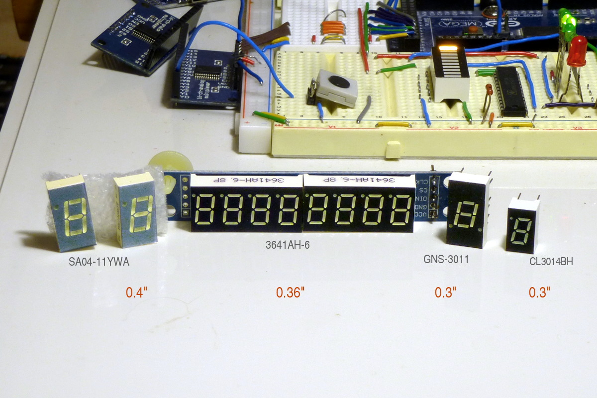
If the sizes of the indicator digits are not suitable for making a display or you do not want to reduce digits number here are a few options:
First, you can simply desolder the 7-segment indicators from the MAX7219 module and use other indicators. This needs some skills.
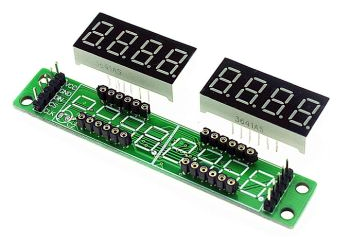
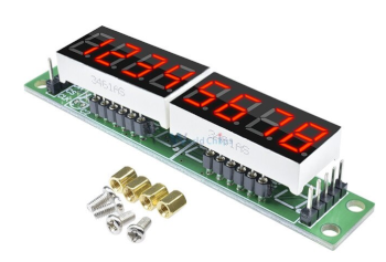
But you can try to find max7219 modules with detachable indicators on the market. Then use any other 7-segment LEDs of the size and color you want. Here is an exaples of such module:
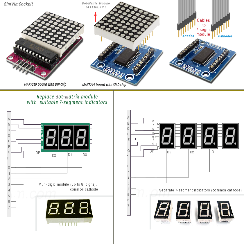
Another alternative is buying a MAX7219 LED matrix board with detachable LED matrix and use it.
The module has row and column connectors that are very convenient to use with 7-segment modules. Remove the LED matrix module and use any suitable 7-segment indicators instead (up to 8-digits).
You can buy one of the MAX7219 dot matrix modules here (example link, just $1 for piece).
If you are qualified enought in electronics, you can buy a driver chip and assemble your display accordingly with the MAX7219 driver specification, using appropriate 7-segment indicators.
The same you can do using DM13A drivers or 74HC595 registers as described below.
One of the easiest ways to drive 7-segment indicators is using the same LED driver ICs as for extended digital output in SimVimX . This is convenient way to make any 7-segment display with any number of digits and digits size. With one driver you can make a 2-digit display, with two - 4-digit etc. See more details below about indicators assembled on DM13A drivers.
Trying this takes only a few minutes of your time, all you need is to take one DM13A driver or another similar IC and two 7-segment indicators. Also one constant or variable resistor 2 .. 10 kΩ is needed to set the desired brightness. Note: the indicators should have a common anode.
Thus, with a single driver, you can quickly assemble a 2-digit display, for example, for a voltage indicator. Adding more drivers to the chain, as shown in the diagram, you will get a display with any number of digits, from 2 to 8 for use with SimVimX . Each IC in the chain drives 2 digits, and the last one - either one or two, depending on your needs.
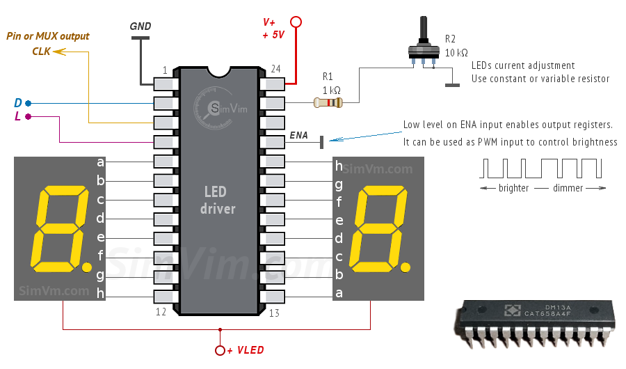
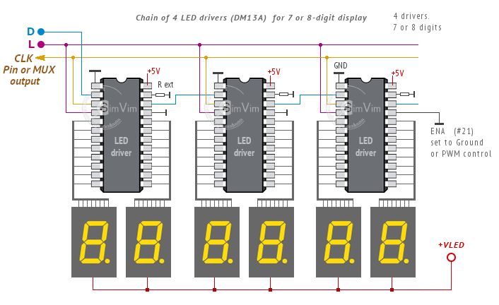
Once the display module is assembled, connect the "CLK" input to the output pin or MUX output assigned for this 7-segment display and two other signal inputs - "D" and "L" - to the common "D" and "L" output bus lines, as described on the system architecture page.
Note: You can power the driver chip from the same +5V bus as your Arduino, but you should use appropriate power supply for the 7-segment indicators (+VLED). It can be a separate power supply or the same +5V source if it is powerful enough for all devices in your system.
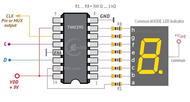
Another option is to use the 74HC595 shift registers, which was implemented in ArdSimX. The difference from LED drivers is that one HC595 chip can drive one 7-segment indicator and it needs 8 resistors for each segment to be connected. The indicators should have a common cathode.
Note: You can use 7-segment indicators with common anode as well, connect the common anode terminal to +Vled power supply and selecting the related type in the configurator.
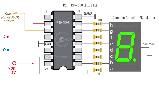
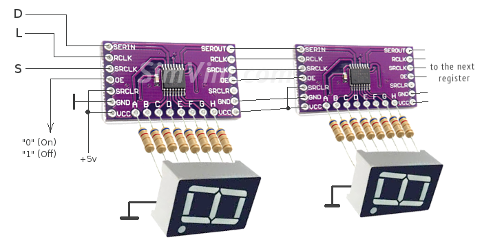
So, with a single chip, you can assemble a 1-digit display. Adding more registers to the chain, you will get a display with any number of digits. When joining several registers, you should connect together all "L" and "CLK" signals.
You can wire registers directly to the indicators or make a printed board. Another option is buying breakout boards with 74HC595 registers. You can find sample links on the "Components" page. All you need is to solder LED indicators with resistors to the board outputs.