
You can assign PWM-controlled devices which are connected directly to one of these mega2560 controller pins - from 2 to 13, and 44,45,46. In the Configurator, select the needed parameter for output and select one of these free pin.
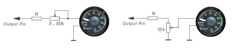
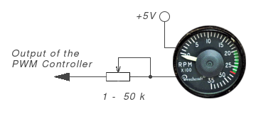
Connect an ammeter to the PWM output of the controller through a current limiting resistor, with the other wire of the gauge connected to the ground. The resistor can be varied from 5 to 100 kOhm depending on the gauge you will use. You can select a suitable resistors by checking the range of the gauge needle. The simplest option you can use just one limiting resistor. Here are the connection options of the coil gauge:
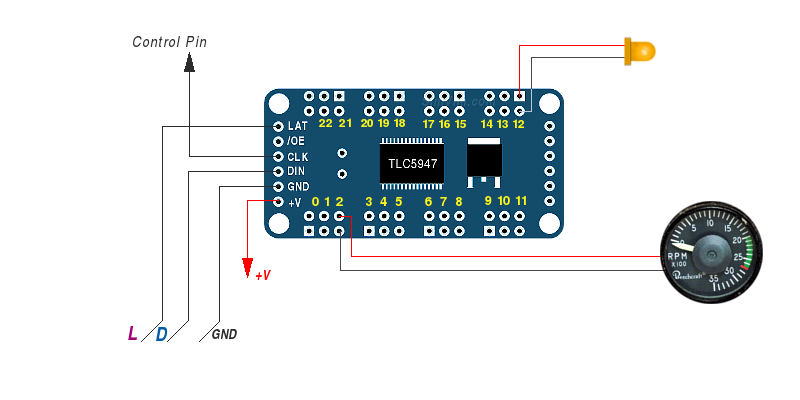
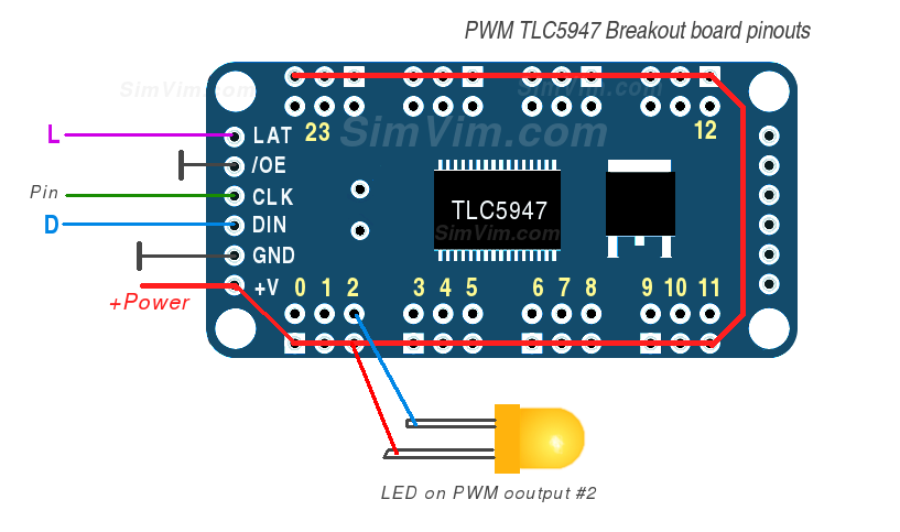
You can use one 24-channel PWM driver (TLC5947) with CLK signal connected to one of these mega2560 controller pins: 30 - 37.
To "connect" the TLC5947 driver in the configurator, click one pin to which the CLK signal of the PWM driver will be connected (pins #30-37 only) and select "PWM Driver" in the "CONNECT:" submenu. Two other control signals are connected to corresponding D and L signals of the system bus. +V is the driver powering input, you can either use +5v from the bus or connect another external power supply.
In this case when choosing a parametr for output in the Configurator, you need to select the PWM controller output number (one of 24 outputs).
Unlike direct connection, the gauge's "+" output is connected to +5V, and "-" is connected to the signal, not to GND.
To assign any specific parameter for output to the gauge, find this parameter in the configurator database and select it for PWM output (either directly connected to the pin, or to any of 24 PWM driver output).
Before using the moving-coil gauge in your cockpit you need to calibrate it. Use the convenient Calibration Tool in the SimVimX plugin to correctly map the data value range on the gauge dial.
You should definitely take in account such device as moving-coil ammeter, widely known for more than 100 years as D'Arsonval galvanometer (which is a moving coil of wire rotated in radial magnetic field).
This meter is very commonly used in various instruments based on current measurement (ammeters, voltmeters, ohmmeters). You can get more information about it yourself.
Moving coil meters can be easily used in your cockpit simulator for many instruments: engine and fuel gauges, electric systems indicators, VOR and glide slope needles, and any others with suitable deflection range (moving-coil ammeters may have needle deflection from 90 to 200+ degrees).
You can find some of the ammeters or voltmeters that can be used without any alteration, except the faceplate for your gauge and the needle (you can just glue your custom needle directly to the meter's needle).
You should pay attention to maximum deflection range - if this is an ammeter, it can be 1 ... 100 mA, if this is a voltmeter, the maximum measuring value should be 1 .. 5V. If you have the meters with these ranges you can use them without reworking:
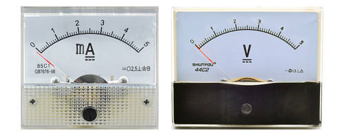
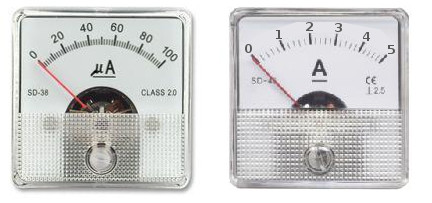
Typically, an ammeter without any shunts inside may have full scale deflection at current of 0.1 to 1mA. If you have an ammeter, for example, with 5A range, you can use it too, but you need to open it and remove the shunt inside (generally, it is just a wire resistor).
It's an easy and convinient way to make some of the engine instruments, electric indcators, some fuel gauges and other instruments that have a limited needle rotation angle (moving-coil ammeters can have the scale varied from 90 to 200 degrees).
Before using your coil gauge you need to know its milliammeter characteristics and calibrate it using resisors/potentiometers.
Video - example of using an old ammeter as PWM gauge controlled by RPM dataref from ARDref plugin (I've used a single potentiometer to adjust the gauge range):
You can notice that the coil meter is moving very smoothly, without jerking and noise (zero noise) and it's very similar to the real gauge in comparison to servo-driven gauges.
Along with digitally controlled LED bar displays (described here), you can use some of analog LED bar display modules with built-in drivers (like LM3914N) which are used as voltage meters and can be controlled with PWM outputs.